
Method and apparatus for a bidirectional meter proving system

a meter and sphere technology, applied in the direction of testing/calibration apparatus, measurement devices, instruments, etc., can solve the problems of increasing operating costs, and achieve the effects of reducing pressure drop, increasing operating costs, and being less expensive to opera

Active Publication Date: 2017-02-28
WFMS
View PDF50 Cites 7 Cited by
  • Summary
  • Abstract
  • Description
  • Claims
  • Application Information

AI Technical Summary

Benefits of technology

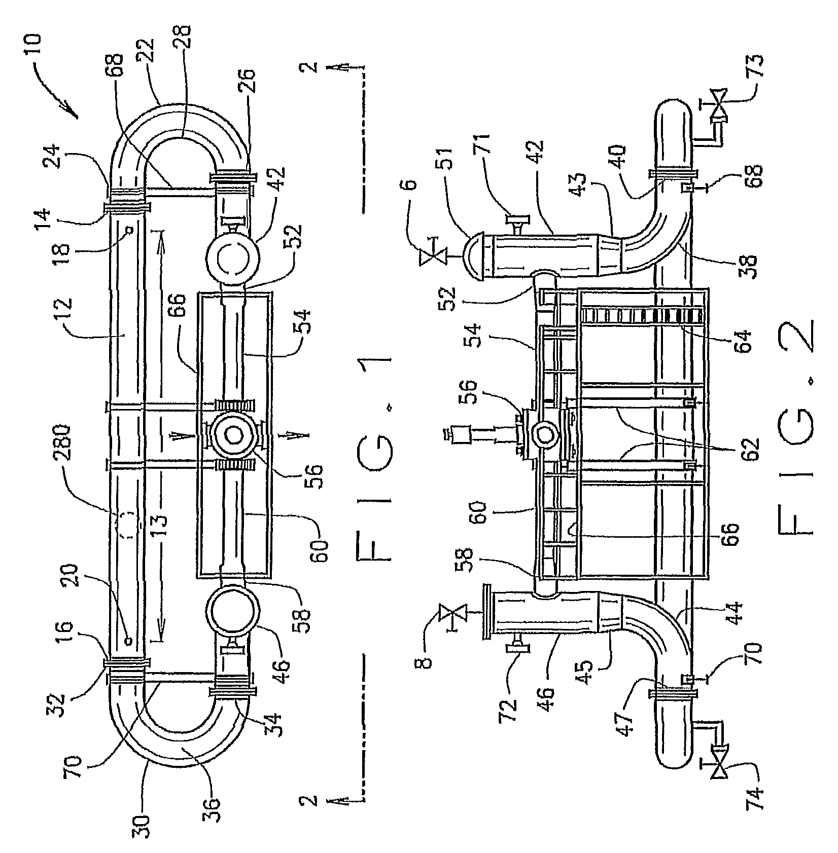
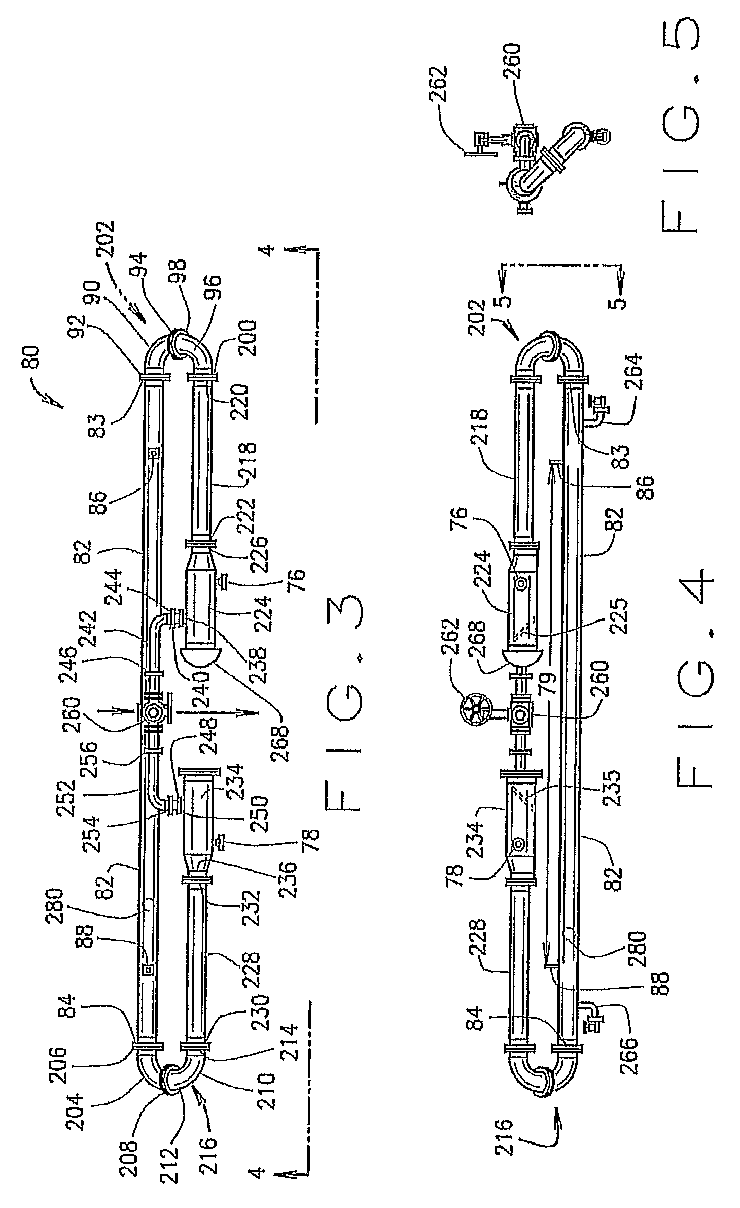
[0029]The straight run of calibrated pipe in the present invention is free of flanges, welds, elbows and other impediments used in the prior art. The bidirectional sphere prover may be used to prove meters that measure liquids, such as crude oil and gasoline. The invention has numerous advantages over the prior art. First it is more accurate. The present invention will allow the custody transfer meter to produce about 10,000 pulses which are substantially evenly spaced between each other. The present invention will allow the sphere to move at a substantially constant velocity between the detector switches. Second, the invention has reduced pressure drop which makes it less expensive to operate. (Pressure drop is a negative feature in liquid transportation systems which increases operating costs.) Third, the invention is cheaper to produce because there is no need for raised face weld neck forged steel flanges which are commonly referred to as machined flanges or superior quality elbows which are expensive. When coriolis and ultra sonic meters are being used, the calibrated straight section of pipe is shorter than prior art bidirectional sphere provers. Fourth, the invention can be inspected in the field without recalibrating using a water draw, which is a substantial operational saving. Fifth, there is no modification to the integrity of the components, unlike the prior art, because the invention may be produced from standard unaltered flanges and elbows.

Problems solved by technology

(Pressure drop is a negative feature in liquid transportation systems which increases operating costs.)

Method used


Image

  • Method and apparatus for a bidirectional meter proving system
  • Method and apparatus for a bidirectional meter proving system
  • Method and apparatus for a bidirectional meter proving system

Examples


Embodiment Construction

[0063]Referring now to FIGS. 1 and 2, the bidirectional sphere meter proving system of the present invention is generally identified by the numeral 10. A straight piece of pipe 12 has a first flange 14 and an opposing second flange 16 on the ends. The flanges 14 and 16 are not altered by machining nor are any of the other flanges in the present invention. Prior art provers require machined flanges in the calibrated sections of piping; the present invention does not use flanges in the calibrated section of piping and does not require machined flanges anywhere else in the prover. Those skilled in the art know that machined flanges are much more expensive than standard flanges. A first detection switch 18 and a second detection switch 20 are positioned in the pipe 12 to indicate when the sphere 280, shown in phantom, passes through the straight calibrated section 13 of conduit 12. The straight calibrated section 13 is free of welds, flanges and elbows. The internal circumference of the...


PUM


Abstract

During a water draw test, horizontal type bidirectional sphere provers with a straight calibrated section of pipe between the detector switches sometimes suffer from sphere launch failure which typically results in a failed water draw test. These types of provers, especially in larger pipe diameters will benefit from an elongate concentric fabricated reducer attached to the outlet of each launch tube. These elongate concentric fabricated reducers result in a successful sphere launch on the first attempt. Assuming all the other components of the prover are properly designed and assembled, a successful sphere launch will result in a successful water draw test on the first attempt saving time, money and reputation.

Description

CROSS-REFERENCE TO RELATED APPLICATION[0001]This is a continuation-in-part of U.S. patent application Ser. No. 13 / 934,209 filed on Jul. 2, 2013 for a Method and Apparatus for a Bidirectional Meter Proving System, now pending, which is a divisional of U.S. Pat. No. 8,505,355 for a Method and Apparatus for a Bidirectional Meter Proving System, which issued on Aug. 13, 2013. Both are hereby incorporated by reference in their entireties to the extent permitted by law.DESCRIPTION OF THE PRIOR ART[0002]When crude oil is being offloaded from a tanker, a custody transfer typically takes place and ownership of the crude oil changes hands. Likewise, money changes hands and an accurate volumetric measurement of the crude oil is required. A lease automatic custody transfer unit (L.A.C.T.) also known as a Petroleum Metering System is typically used to measure the crude oil or other fluids. Those skilled in the art know that a L.A.C.T. unit typically includes a sampler, a strainer, a custody tran...

Claims


Application Information

Patent Timeline
Patent Type & Authority Patents(United States)
IPC IPC(8): G01F25/00
CPCG01F25/0015G01F25/11
Inventor RUDROFF, DANIEL J.
Owner WFMS
Learn More