Accessory for lifting and bonding wire cable trays

a technology for splicing and wire cables, which is applied in the direction of suspension devices, domestic objects, machine supports, etc., can solve the problems of inability to mount known raising accessories in advance on the cable tray, high cost of pre-mounting time, and inability to provide devices known from the prior art to provide, etc., to achieve convenient manufacturing, improve locking, and reduce production costs

Active Publication Date: 2008-12-23
LEGRAND SNC
View PDF5 Cites 34 Cited by
  • Summary
  • Abstract
  • Description
  • Claims
  • Application Information

AI Technical Summary

Benefits of technology

[0012]In this way the feet of the device according to the invention make it possible to raise a cable tray which bears on the upper face of the device. The first housings of the upper face are each adapted to receive a weft wire. The accessory according to the invention may thus receive the two ends, placed facing each other, of two wire cable trays to form a splice. The other housing may then receive either two warp wires in the case of forming a splice, or a single warp wire in the other cases. The locking means then make it possible to join one cable tray or (in the case of forming a splice) two cable trays with the accessory.
[0015]In a preferred embodiment, each locking device comprises a tab that can be folded down associated with a housing, the tab, in its non folded down position, enabling a wire to be placed in the corresponding housing and in its folded down position enabling the wire to be held in its housing. This embodiment makes it possible to lock a wire (warp or weft) easily and rapidly in its housing and also enables pre-mounting of the accessory according to the invention on a cable tray. In this embodiment, the tab advantageously has a substantially rectangular cut-out enabling the end of a flat-bladed screwdriver to be inserted in order to bring the tab into locked position.
[0019]In the preferred embodiment, the accessory according to the invention takes the form of a part having a profiled cross-section substantially the shape of an inverted U, the branches of the U forming the legs of the accessory, and the base of the U the upper face thereof. Such a part may easily be manufactured and is of low production cost.

Problems solved by technology

The devices known from the prior art are not intended to provide at the same time the raising and the splicing together of two cable trays.
Furthermore, the known raising accessories most often cannot be mounted in advance on the cable tray for which they are intended.
Such a pre-mounting is costly in terms of time.

Method used


Image

  • Accessory for lifting and bonding wire cable trays
  • Accessory for lifting and bonding wire cable trays
  • Accessory for lifting and bonding wire cable trays

Examples


Embodiment Construction

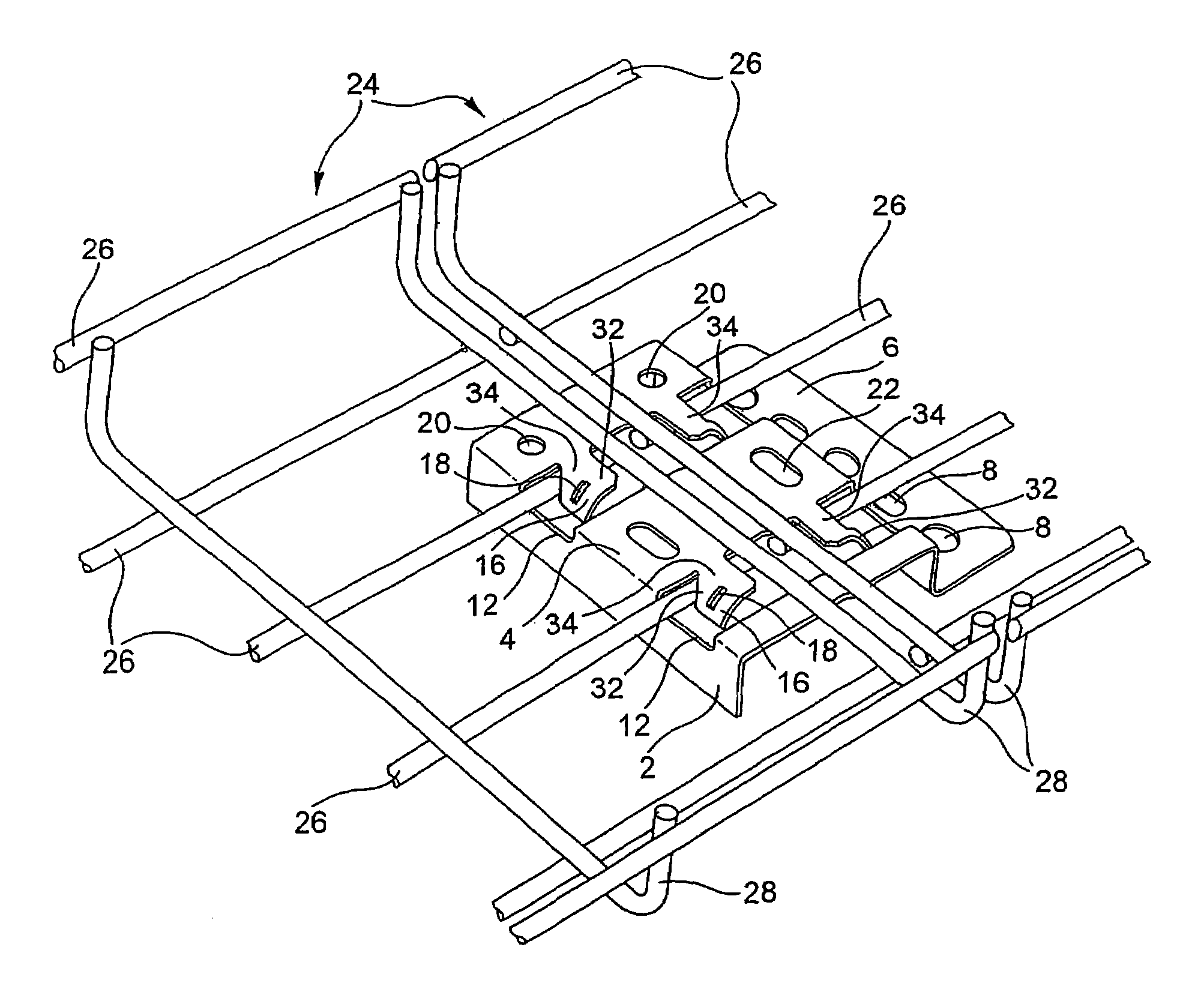
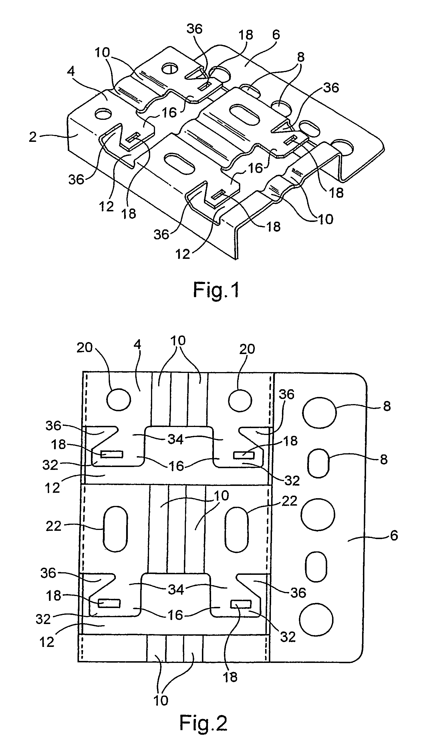
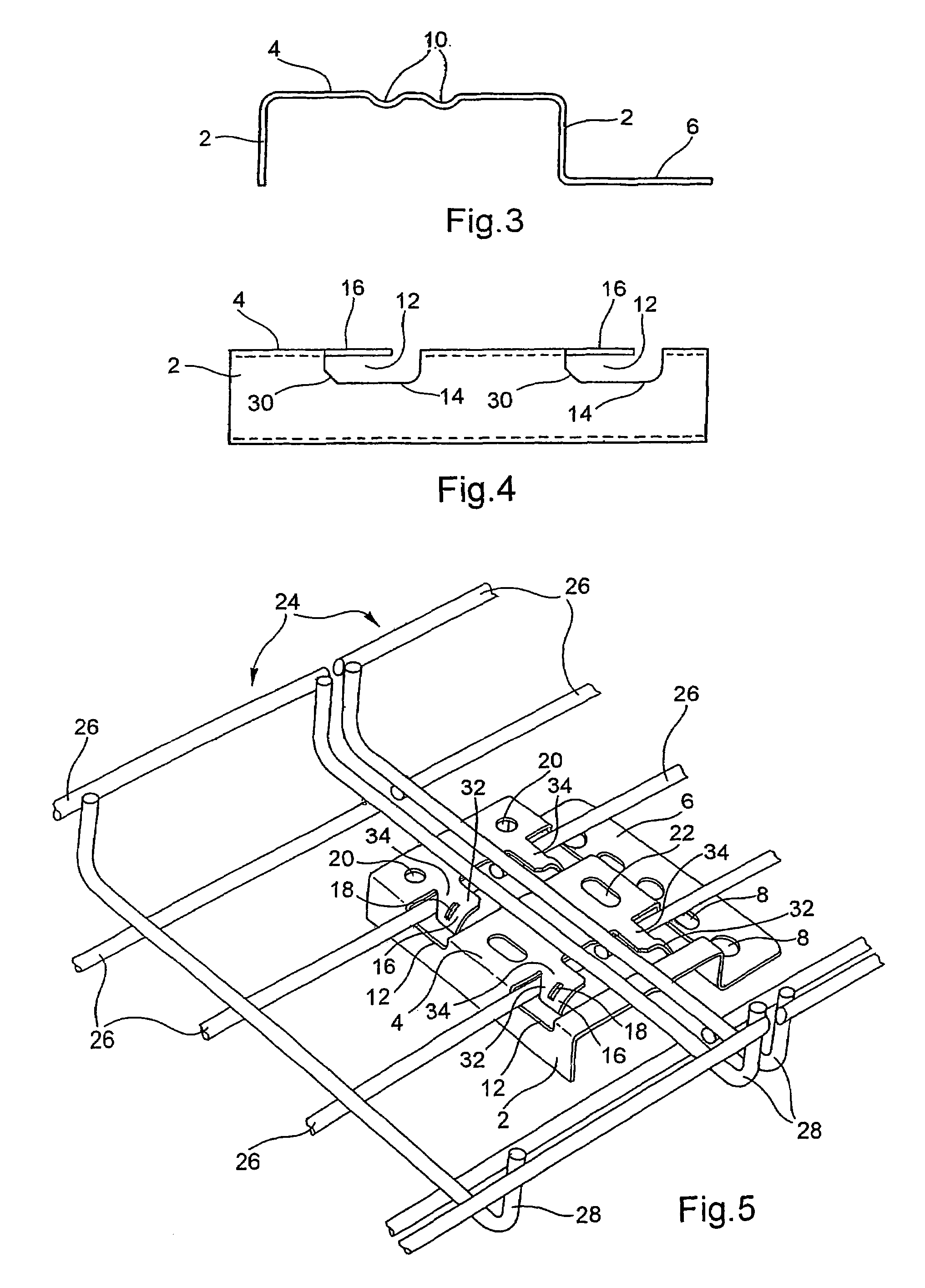
[0027]The accessory represented in the drawing has the form of a metal part of profiled section produced from sheet metal that is cut out and folded. By way of indication, the thickness of the sheet metal is of the order of a millimeter. The material used is for example steel and the sheet metal is for example treated by continuous galvanization using the Sendzimir™ process.

[0028]This part of profiled section has the general form of an inverted U thus forming a bridging member. The branches of the U form two feet 2 and an upper face 4. It is assumed in what follows in the description that the feet 2 are substantially vertical and the upper face 4 substantially horizontal. The feet 2 are adapted to rest on a substantially flat floor and make it possible to keep the upper face 4 spaced apart from that floor and parallel thereto.

[0029]As can be seen in the drawings, a foot 2 is provided with a rim 6. This latter is formed at the end of the foot 2 concerned, remote from the upper face 4...


PUM


Abstract

This accessory is intended for wire cable trays comprising longitudinal warp wires and transverse weft wires linking the warp wires, the wire cable tray having a bottom adapted to receive electric cables or the like and two side flanges.The accessory comprises an upper face (4) raised by at least two feet (2).The upper face (4) comprises not only two first housings (10) disposed parallel to each other and each adapted to receive a weft wire but also at least one housing (12) substantially perpendicular to the first two housings (10).At least one locking device (16) is provided on each side of a median line between the first two housings (10).

Description

FIELD OF THE INVENTION[0001]The present invention relates to an accessory for raising and splicing together wire cable trays.[0002]The field of the invention is the mounting and splicing together of wire cable trays. Cable trays are used to ensure the support, housing and protection of longilinear items such as electric cables or tubes, for example pneumatic or hydraulic connecting tubes.BACKGROUND OF THE INVENTION[0003]A wire cable tray generally has an elongate form and is of U-section. It comprises longitudinal wires, also termed warp wires, and transverse wires, also termed weft wires. The warp wires are generally straight and the weft wires are U-shaped. The weft wires are welded to the warp wires and are regularly spaced. The cable tray so produced has a bottom adapted to serve as a support for the cables or the like, and side walls, or flanges, adapted to hold the cables on the bottom.[0004]In all that follows, for the sake of simplicity and clarity, the description will be m...

Claims


Application Information

Patent Timeline
Patent Type & Authority Patents(United States)
IPC IPC(8): H02G3/04H02G3/06
CPCH02G3/0443H02G3/0608
Inventor DECIRY, JAMESQUERTELET, STEPHANE
Owner LEGRAND SNC
Why Eureka
Try Eureka