Method and apparatus to control display brightness with ambient light correction

a technology of ambient light correction and display brightness, applied in the field of methods, can solve the problems of affecting the reading of the display, affecting the use of the display, and the long life of light sources between failures,

Active Publication Date: 2008-12-23
POLARIS POWERLED TECH LLC
View PDF376 Cites 53 Cited by
  • Summary
  • Abstract
  • Description
  • Claims
  • Application Information

AI Technical Summary

Benefits of technology

[0008]In one embodiment, the present invention is a light sensor control system that provides the capability for a fully automatic and fully adaptable method of adjusting display brightness in response to varying ambient lighting conditions in combination with various user preferences. For example, the mathematical product of a light sensor output and a user selectable brightness control can be used to vary backlight intensity in LCD applications. Using the product of the light sensor output and the user selectable brightness control advantageously offers noticeable user dimming in bright ambient levels. Power is conserved by automatically dimming the backlight in low ambient light levels. The user control feature allows the user to select a dimming contour which works in conjunction with a visible light sensor.
[0010]In one embodiment, a backlight system with selective ambient light correction allows a user to switch between a manual brightness adjustment mode and an automatic brightness adjustment mode. In the manual mode, the user's selected brightness preference determines the backlight brightness, and the user dims or increases the intensity of the backlight as the room ambient light changes. In the automatic mode, the user adjusts the brightness level of the LCD to a desired level, and as the ambient light changes, the backlight automatically adjusts to make the LCD brightness appear to stay consistent at substantially the same perceived level. The automatic mode provides better comfort for the user, saves power under low ambient lighting conditions, and prevents premature aging of light sources in the backlight system.
[0011]The mathematical product of a light sensor output and a user selectable brightness control can be similarly used to vary brightness in cathode ray tube (CRT) displays, plasma displays, organic light emitting diode (OLED) displays, and other visual information display systems that do not use backlight for display illumination. In one embodiment, a brightness control circuit with ambient light correction includes a visible light sensor that outputs a sensor current signal in proportion to the level of ambient light, a dimming control input determined by a user, and a multiplier circuit that generates a brightness control signal based on a mathematical product of the sensor current signal and the dimming control input. The brightness control signal is provided to a display driver (e.g., an inverter) to adjust brightness levels of one or more light sources, such as cold cathode fluorescent lamps (CCFLs) or light emitting diodes (LEDs) in a backlight system. The brightness control circuit with ambient light correction advantageously improves ergonomics by maintaining consistent brightness as perceived by the human eye. The brightness control circuit with ambient light correction also reduces power consumption to extend battery life and reduces stress on the light sources to extend product life at low ambient light levels.
[0012]In various embodiments, the brightness control circuit further includes combinations of a dark level bias circuit, an overdrive clamp circuit, or an automatic shutdown circuit. The dark level bias circuit maintains the brightness control signal above a predetermined level when the ambient light level decreases to approximately zero. Thus, the dark level bias circuit ensures a predefined (or minimum) brightness in total ambient darkness. The overdrive clamp circuit limits the brightness control signal to be less than a predetermined level. In one embodiment, the overdrive clamp circuit facilitates compliance with input ranges for the display driver. The automatic shutdown circuit turns off the light sources when the ambient light is greater than a predefined level. For example, the automatic shutdown circuit saves power by turning off auxiliary light sources when ambient light is sufficient to illuminate a transflective display.

Problems solved by technology

The ability to read the display is hampered under conditions of high ambient room lighting.
Typically, the light sources have a longer lifetime between failures if they run at lower brightness levels.
These systems usually do not take into account user preferences.
These systems are crude in implementation and do not adapt well to user preferences which may vary under various levels of eye fatigue.

Method used


Image

  • Method and apparatus to control display brightness with ambient light correction
  • Method and apparatus to control display brightness with ambient light correction
  • Method and apparatus to control display brightness with ambient light correction

Examples


Embodiment Construction

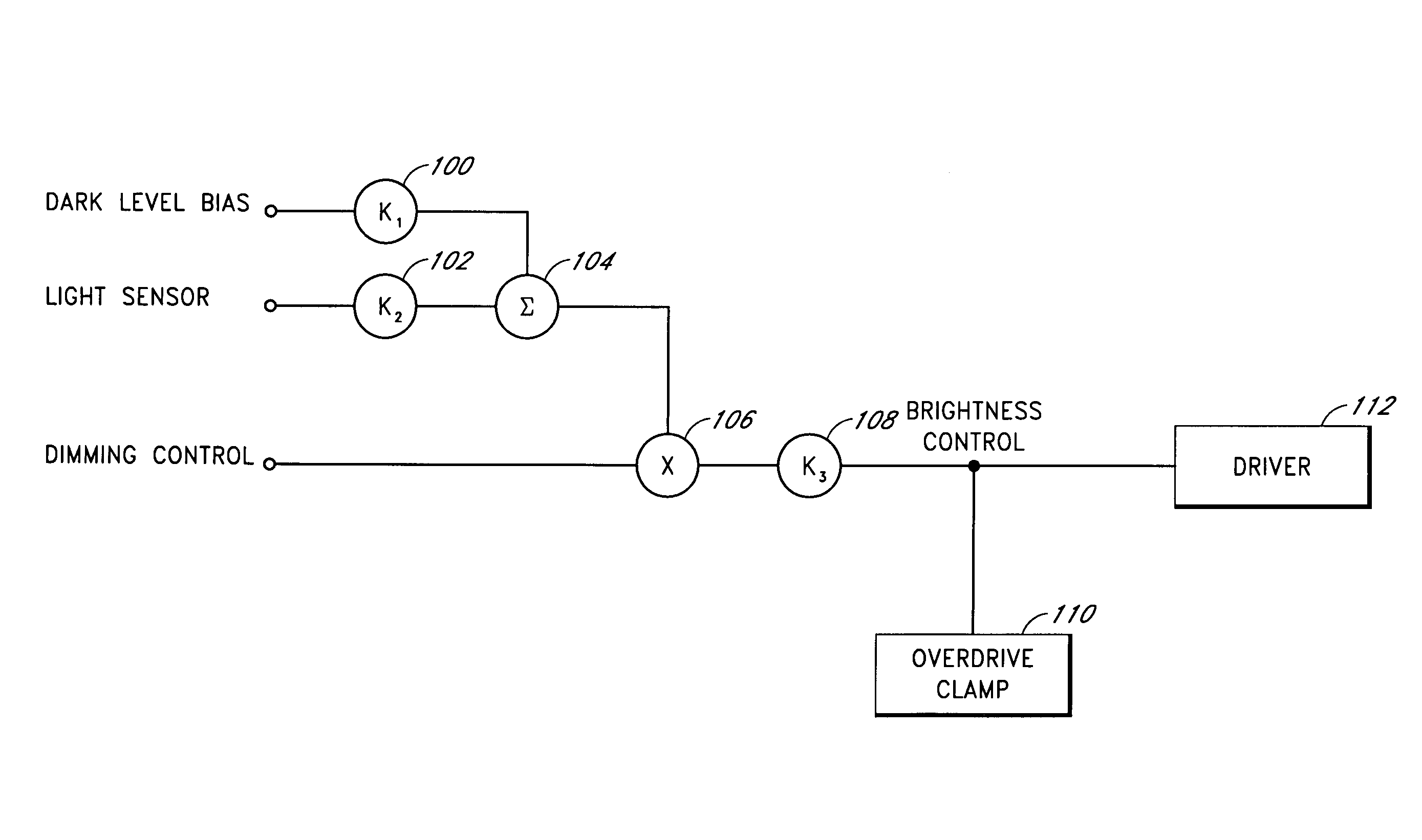
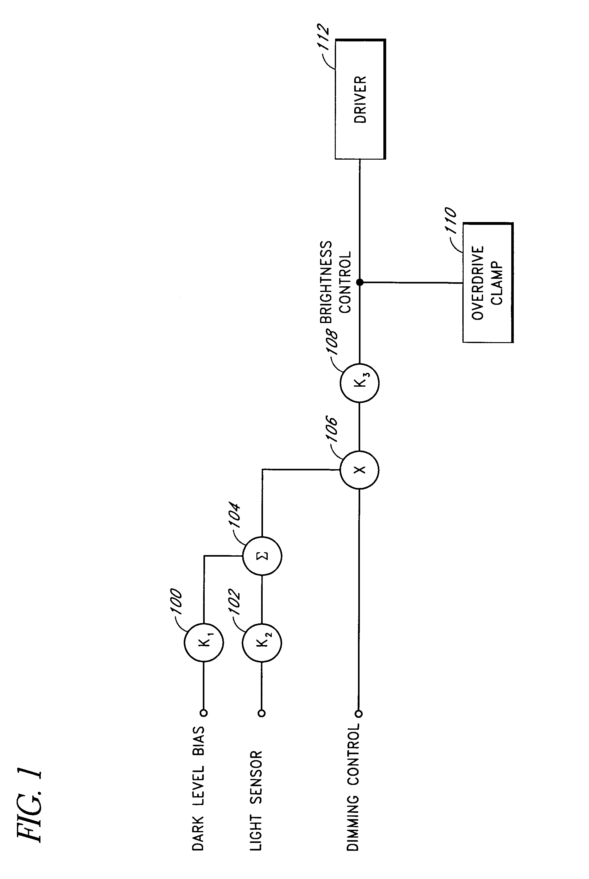
[0030]Embodiments of the present invention will be described hereinafter with reference to the drawings. FIG. 1 is a block diagram of one embodiment of a brightness control circuit with ambient light correction. A user input (DIMMING CONTROL) is multiplied by a sum of a dark level bias (DARK LEVEL BIAS) and a light sensor output (LIGHT SENSOR) to produce a brightness control signal (BRIGHTNESS CONTROL) for a display driver 112. In one configuration, the dark level bias and the light sensor output are adjusted by respective scalar circuits (k1, k2) 100, 102 before being added by a summing circuit 104. An output of the summing circuit 104 and the user input is provided to a multiplier circuit 106. An output of the multiplier circuit 106 can be adjusted by a third scalar circuit (k3) 108 to produce the brightness control signal. An overdrive clamp circuit 110 is coupled to the brightness control signal to limit its amplitude range at the input of the display driver 112.

[0031]The displa...


PUM


Abstract

An ambient light sensor produces a current signal that varies linearly with the level of ambient light. The current signal is multiplied by a user dimming preference to generate a brightness control signal that automatically compensates for ambient light variations in visual information display systems. The multiplying function provides noticeable user dimming control at relatively high ambient light levels.

Description

CLAIM FOR PRIORITY[0001]This application claims the benefit of priority under 35 U.S.C. § 119(e) of U.S. Provisional Application No. 60 / 543,094, filed on Feb. 9, 2004, and entitled “Information Display with Ambient Light Correction,” the entirety of which is incorporated herein by reference.BACKGROUND OF THE INVENTION[0002]1. Field of the Invention[0003]The present invention relates to brightness control in a visual information display system, and more particularly relates to adjusting the brightness level to compensate for changes in ambient lighting.[0004]2. Description of the Related Art[0005]Backlight is needed to illuminate a screen to make a visible display in liquid crystal display (LCD) applications. The ability to read the display is hampered under conditions of high ambient room lighting. Ambient lighting reflects off the surface of the LCD and adds a bias to the light produced by the LCD, which reduces the display contrast to give the LCD a washed-out appearance. The cond...

Claims


Application Information

Patent Timeline
Patent Type & Authority Patents(United States)
IPC IPC(8): G09G3/36G09G3/22G09G3/34G09G5/00
CPCG09G3/3406G09G3/22G09G3/36G09G2300/0456G09G2320/0606G09G2320/0626G09G2360/144
Inventor FERGUSON, BRUCE R.
Owner POLARIS POWERLED TECH LLC
Why Eureka
Try Eureka