Vacuum apparatus

a vacuum apparatus and vacuum technology, applied in the direction of measuring devices, structural/machine measurement, instruments, etc., can solve the problems of o-rings that cannot be replaced frequently, o-rings are easily degraded, and maintenance work of o-rings requires a long time, so as to reduce the downtime of the apparatus and the cost.

Inactive Publication Date: 2009-01-06
TOKYO ELECTRON LTD
View PDF11 Cites 18 Cited by
  • Summary
  • Abstract
  • Description
  • Claims
  • Application Information

AI Technical Summary

Benefits of technology

[0007]It is, therefore, a primary object of the present invention to provide a leak rate measuring method capable of precisely measuring a leak rate from a vacuum chamber without a gate valve. It is another object of the present invention to provide a vacuum apparatus having no gate valve at an upstream side of a turbo-molecular pump in a gas flowing direction to thereby reduce the number of maintenance works.
[0016]In accordance with the fifth aspect, since no gate valve is provided at the upstream side of the first exhaust pump, the vacuum apparatus can be achieved without using a readily degradable O-ring necessary for the gate valve mechanism. Accordingly, it is possible to reduce the number of the components as well as the time and costs required for the maintenance such as the replacement of the O-ring, so that the safety of the apparatus can be enhanced.
[0027]In accordance with the present invention, the leak rate of the vacuum chamber can be measured without providing a gate valve adjacent to the conductance variable valve or a gate valve integrated with the conductance variable valve (APC valve having a gate valve mechanism). Accordingly, maintenance work of a readily degradable O-ring required for the gate valve mechanism becomes unnecessary. As a result, it is possible to reduce a downtime of an apparatus and a cost required for the maintenance work.

Problems solved by technology

However, in the vacuum apparatus for performing processes using a plasma, the O-ring is easily degraded by radicals generated during a dry cleaning process or the like and thus needs to be replaced frequently.
A maintenance work of the O-ring requires a long time due to a recent trend towards a large diameter of a gas exhaust line, which leads to an increased downtime of the apparatus.

Method used


Image

  • Vacuum apparatus
  • Vacuum apparatus
  • Vacuum apparatus

Examples


first embodiment

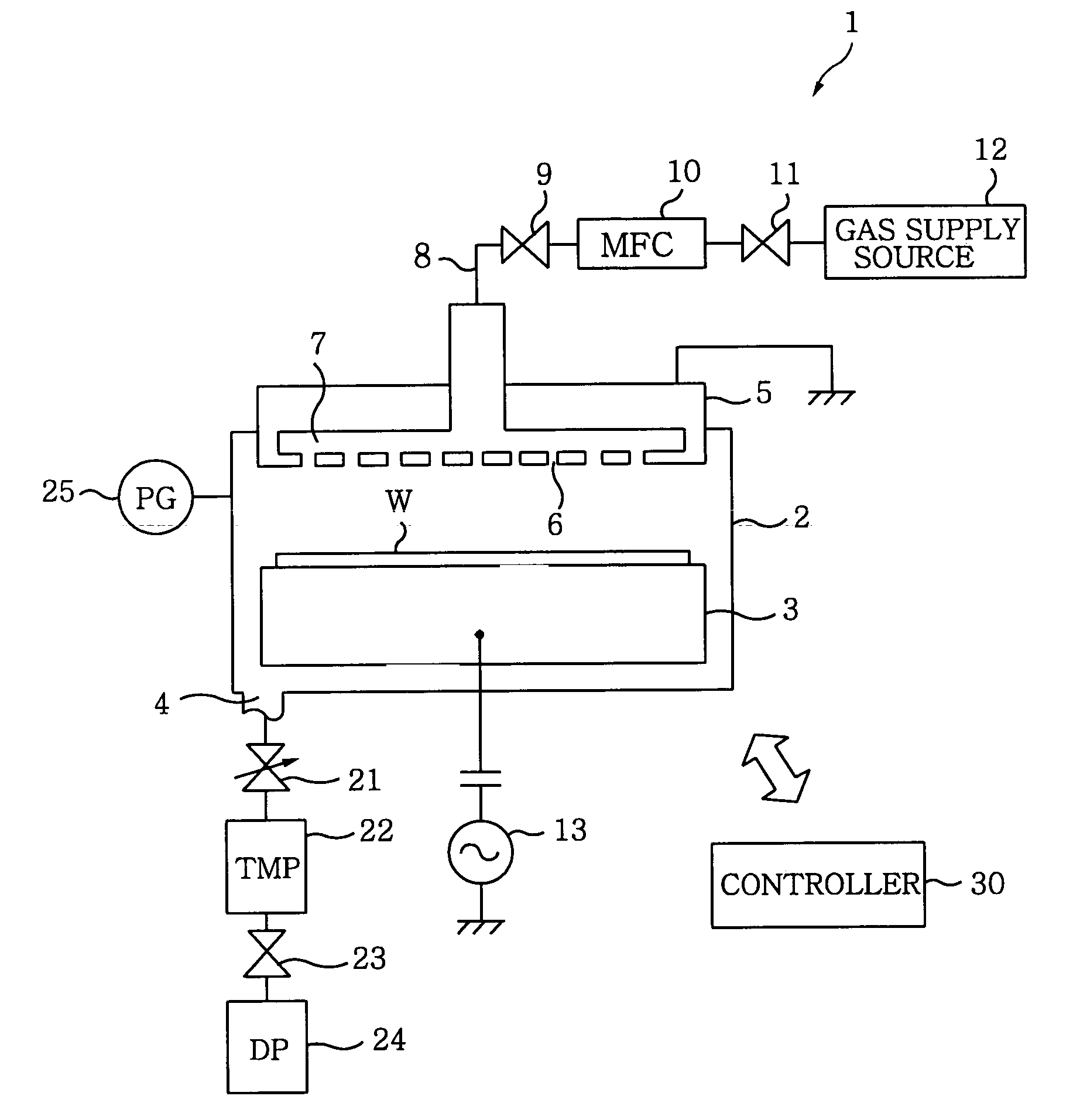
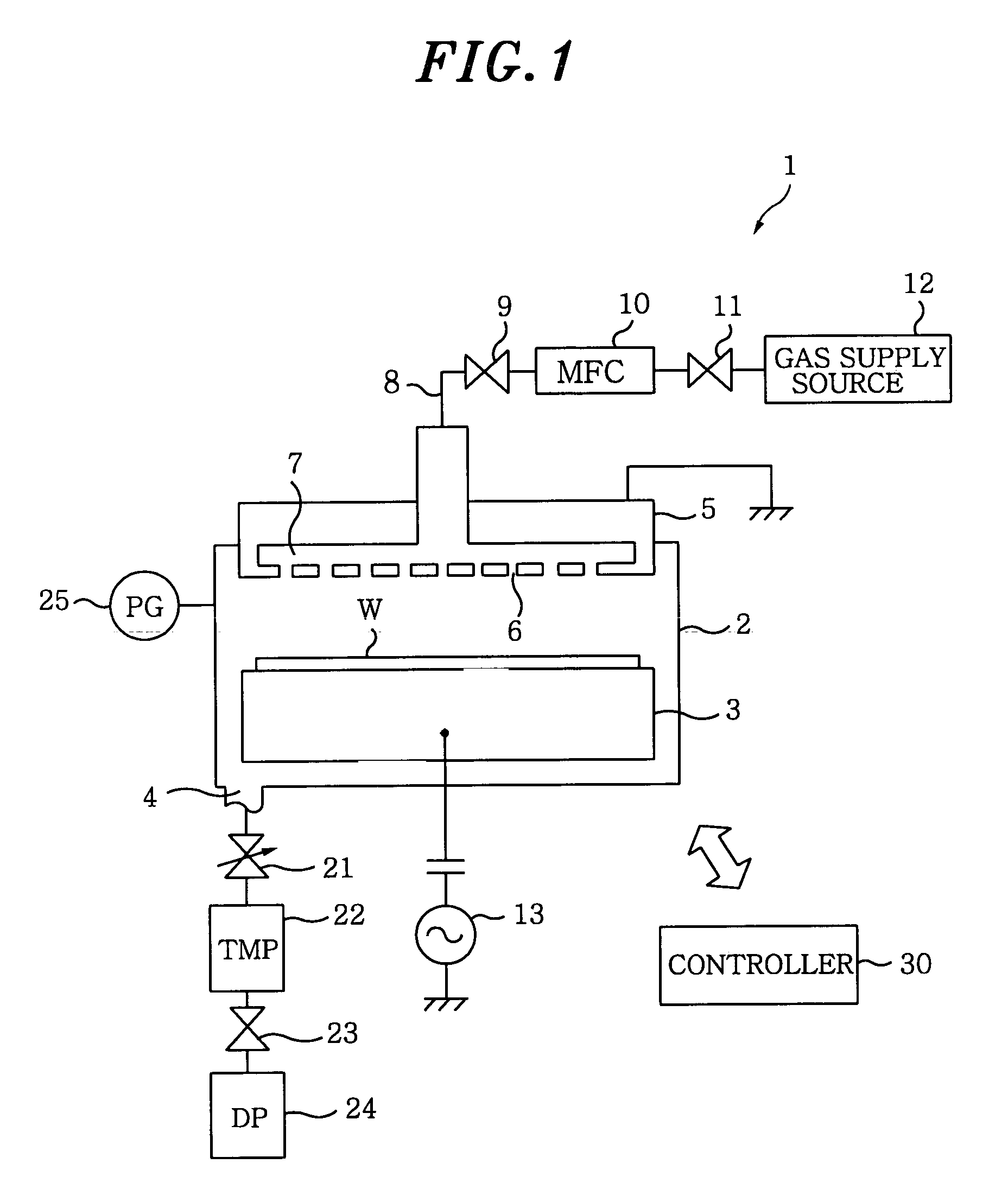
[0096]FIG. 8 is a flowchart showing a control sequence of measuring a leak rate by a leak rate measuring method in accordance with a first preferred embodiment of the present invention; and FIG. 9 presents an operational status of a gas exhaust unit in the measurement of the leak rate in accordance with the first preferred embodiment of the present invention. The open and the closed states of the valves are indicated in white and black color, respectively. Further, the dot-indication means that the valve is opened at a certain degree between the open state and the closed state (This also applies to FIGS. 12, 15 and 18). In a following description, the valve 23 as a second valve may be indicated as a valve V1 for the convenience.

[0097]In this embodiment, there is provided a circulation line 26 branched from a gas exhaust path between the turbo-molecular pump 22 and the valve V1 (the valve 23) and connected to the vacuum chamber 2 to communicate therewith. Further, the leak rate is me...

second embodiment

[0104]FIG. 11 represents a flowchart showing a control sequence of measuring a leak rate by using a leak rate measuring method in accordance with a second preferred embodiment of the present invention. FIG. 12 illustrates an operational status of a gas exhaust unit in the measurement of the leak rate in accordance with the second preferred embodiment of the present invention. In this embodiment, a back pressure of the turbo-molecular pump 22, i.e., a pressure P2 inside a line between the turbo-molecular pump 22 and the valve V1, is monitored with the pressure gauge 27 disposed at the line between the turbo-molecular pump 22 and the valve V1 (the valve 23), thereby measuring the leak rate.

[0105]Referring to FIG. 11, there are illustrated steps S21 to S22 as preparatory sequences prior to measuring a leak rate, and steps S23 to S27 as sequences for measuring the leak rate.

[0106]In this embodiment, before the leak is checked, the turbo-molecular pump 22 and the dry pump 24 are driven, ...

third embodiment

[0109]FIG. 14 offers a flowchart illustrating a control sequence of measuring a leak rate by a leak rate measuring method in accordance with a third preferred embodiment of the present invention; and FIG. 15 describes a state of a gas exhaust unit in the measurement of the leak rate in accordance with the third preferred embodiment of the present invention. In this embodiment, after stopping the turbo-molecular pump 22, a pressure increase inside the vacuum chamber 2 is monitored in a state where the vacuum chamber 2 is completely exhausted by the dry pump 24, thereby measuring a leak rate.

[0110]Referring to FIG. 14, there are illustrates steps S31 and S32 as preparatory sequences prior to measuring a leak rate and steps S33 to S37 as sequences for measuring the leak rate.

[0111]In this embodiment, before the leak is checked, the turbo-molecular pump 22 is stopped and the dry pump 24 is driven. Then, the APC valve 21 is fully opened and the valves V1 and V3 are opened.

[0112]First of ...


PUM


Abstract

A leak rate measuring method measures a leak rate of a vacuum apparatus including a vacuum chamber in which an object is accommodated to be processed, a first gas exhaust pump connected to the vacuum chamber via a first valve serving as a conductance variable valve, and a second valve connected to a downstream side of the first gas exhaust pump in a gas flowing direction. In the leak rate measuring method, there is provided a circulating path branched from a gas exhaust path between the first gas exhaust pump and the second valve and connected to the vacuum pump to communicate therewith. The pressure inside the vacuum chamber is monitored by circulating a gas into the vacuum chamber through the circulating path with first gas exhaust pump under the condition that the first valve is set at a predetermined conductance and the second valve is closed.

Description

FIELD OF THE INVENTION[0001]The present invention relates to a vacuum apparatus for performing an etching process, a film forming process or the like on an object to be processed such as a semiconductor wafer, a method for measuring a leak rate thereof, and a program and a storage medium used in the measurement of the leak rate.BACKGROUND OF THE INVENTION[0002]A vacuum apparatus for performing an etching process, a film forming process or the like in manufacturing various semiconductor devices includes a gas exhaust unit having a valve and a gas exhaust pump. Further, in the vacuum apparatus, a pressure inside a vacuum chamber can be depressurized to a desired vacuum state.[0003]To be specific, a conductance variable adaptive pressure control (APC) valve, a gate valve, a turbo-molecular pump (TMP) as a main gas exhaust pump, a valve and a dry pump as an auxiliary gas exhaust pump are connected to each other in that order from the side of the vacuum chamber, so that the vacuum chambe...

Claims


Application Information

Patent Timeline
Patent Type & Authority Patents(United States)
IPC IPC(8): G01M3/04
CPCG01M3/3236
Inventor KITAZAWA, TAKASHIKOBAYASHI, ATSUSHITEZUKA, KAZUYUKI
Owner TOKYO ELECTRON LTD
Why Eureka
Try Eureka