Radar device
a radar device and a technology for estimating incoming waves, applied in direction finders, radio wave direction/deviation determination systems, multi-channel direction-finding systems using radio waves, etc., can solve the problems of insufficient processing speed of radar devices, insufficient amount of data collection, inaccurate estimation, etc., to achieve accurate estimation of incoming waves
- Summary
- Abstract
- Description
- Claims
- Application Information
AI Technical Summary
Benefits of technology
Problems solved by technology
Method used
Image
Examples
first embodiment
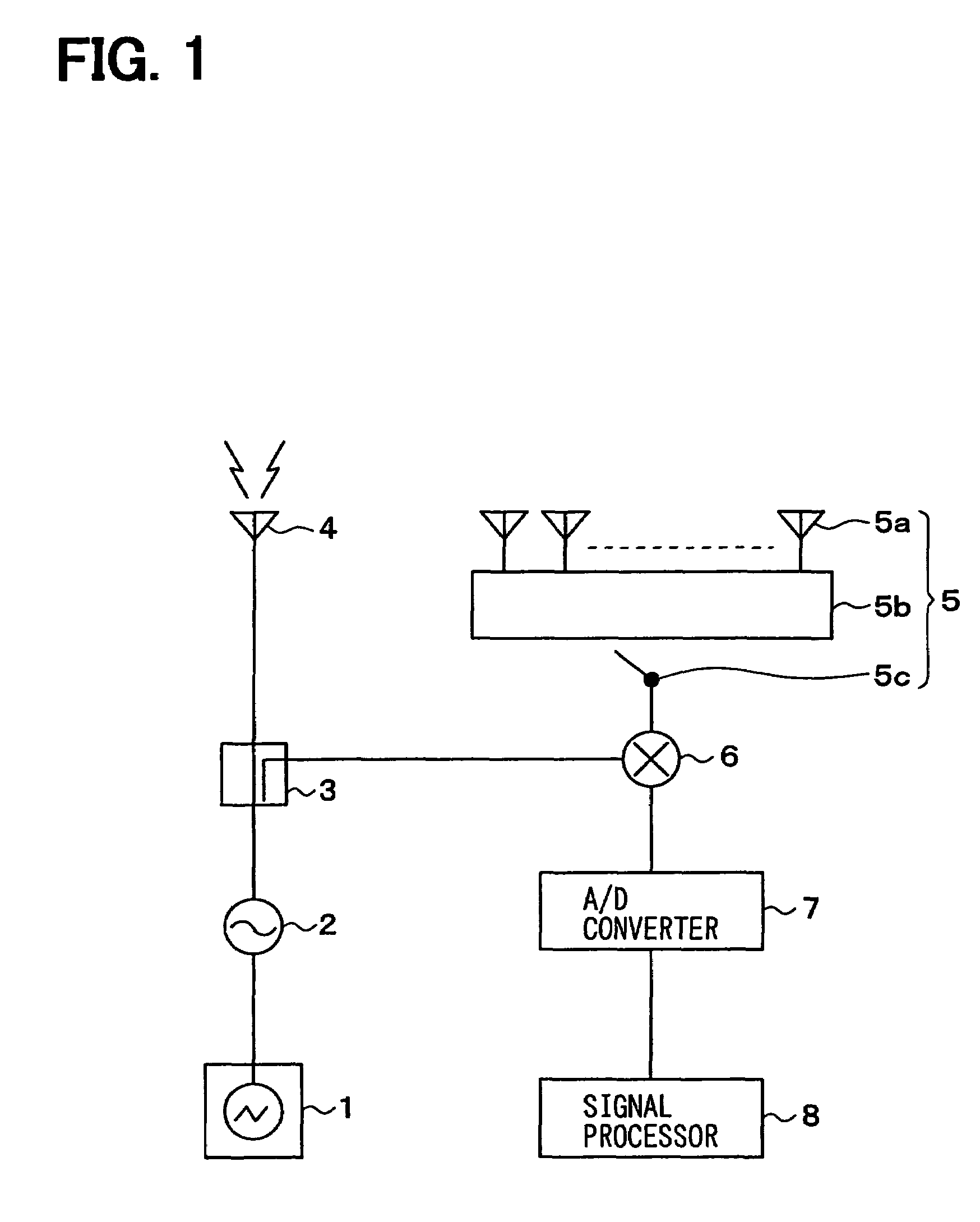
[0044]A first embodiment of the present invention, i.e., a radar device for an automotive use, is shown as a block diagram in FIG. 1.
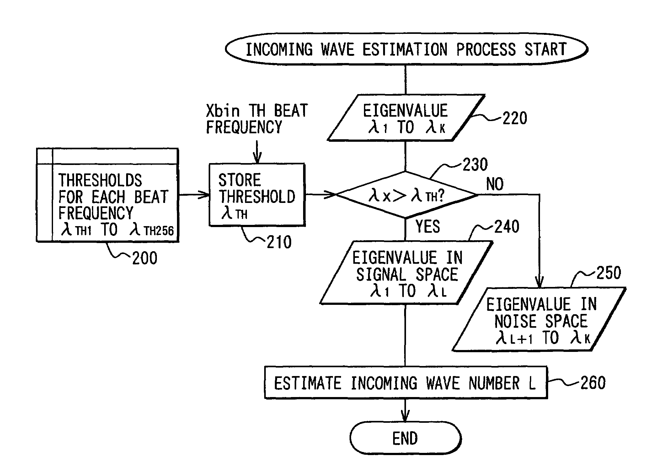
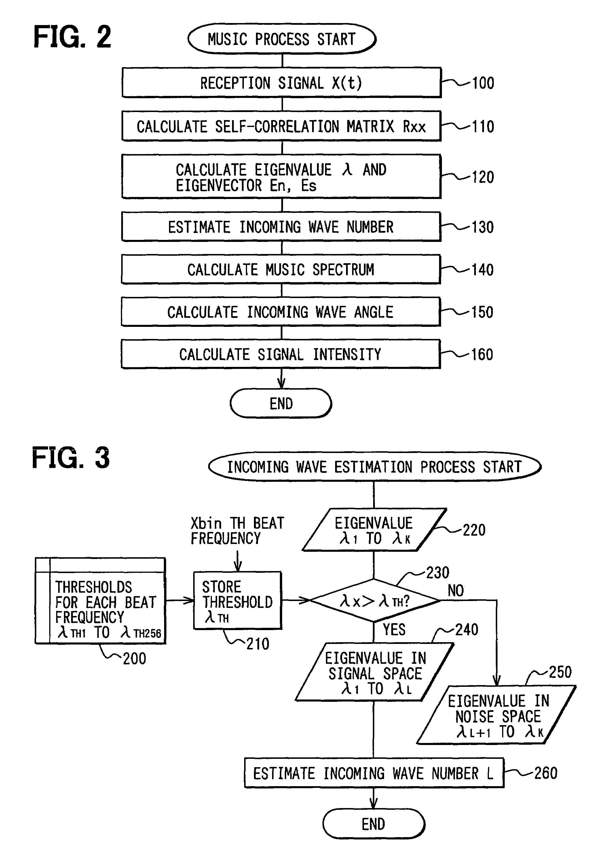
[0045]The radar device transmits a millimetric radio wave toward, for example, a front space of an automobile to detect an object in front of the automobile. The radar device receives an incoming wave reflected by the object to detect a distance and an angle of the object. The radar device estimates the number of the incoming wave and the angle of the wave to calculate a relative speed of the object in a course of detection.
[0046]The radar device includes a modulation signal generator 1, a voltage-controlled oscillator (VCO) 2, a distributor 3, a transmission antenna 4, a receiver 5, a mixer 6, an A / D converter 7 and a signal processor 8.
[0047]The modulation signal generator 1 generates, for example, a modulation signal that is characterized by a linear increase and decrease of frequency in a triangular shape. The modulation signal is outputted to the ...
second embodiment
[0068]A second embodiment of the present invention is described with reference to the drawings. In the second embodiment, the incoming wave estimation process executed by the signal processor 8 in the first embodiment is modified. The other process of the invention remains intact. Therefore, only the modified part is described.
[0069]In the present embodiment, a maximum number of the incoming waves is considered besides sifting the signal from the noise in the incoming wave estimation process. The maximum number is set according to a target detection area of the millimetric wave transmitted from the transmission antenna 4.
[0070]FIG. 5 shows an illustration of automobiles in a target detection area of a radar wave transmitted from a transmission antenna. In this figure, it is perceived that a distance from a subject automobile is a determining factor of the maximum number of automobiles running parallel in the target detection area of the radar device.
[0071]For example, no more than t...
third embodiment
[0078]A third embodiment of the present invention is described with reference to the drawings. In the third embodiment, the incoming wave estimation process executed by the signal processor 8 in the first embodiment is modified. The other process of the invention remains intact. Therefore, only the modified part is described.
[0079]In the third embodiment, the history of detection data is utilized in the incoming wave estimation process for predicting the number of objects detected in a subsequent cycle in addition to determining the maximum number.
[0080]FIG. 7 shows an illustration of positions and movement of the automobiles relative to the subject automobile. In this case, one of the automobiles running in front of the subject automobile catches up with the other automobile in the subsequent cycle of detection.
[0081]In this example, two automobiles are recognized in deferent areas because the beat frequencies from the two automobiles are different. That is, the number of the incom...
PUM
 Abstract
Description
Claims
Application Information
 - R&D
- Intellectual Property
- Life Sciences
- Materials
- Tech Scout
- Unparalleled Data Quality
- Higher Quality Content
- 60% Fewer Hallucinations
Browse by: Latest US Patents, China's latest patents, Technical Efficacy Thesaurus, Application Domain, Technology Topic, Popular Technical Reports.
© 2025 PatSnap. All rights reserved.Legal|Privacy policy|Modern Slavery Act Transparency Statement|Sitemap|About US| Contact US: help@patsnap.com


