Electronically scanned antenna

a technology of electromagnetic scanning and antennas, applied in the direction of antennas, space fed arrays, movable bodies, etc., can solve the problems of complex feed network, loss, and cos

Active Publication Date: 2009-01-06
RAYTHEON CO
View PDF10 Cites 18 Cited by
  • Summary
  • Abstract
  • Description
  • Claims
  • Application Information

AI Technical Summary

Benefits of technology

[0002]An electronically scanned antenna includes a plurality of space-fed, contiguous subarrays arranged in an annular region. Each subarray includes an inner set of radiating elements facing inwardly, an outer-facing set of radiating elements, and a fe

Problems solved by technology

However, for a high power large circular array, the corporat

Method used


Image

  • Electronically scanned antenna
  • Electronically scanned antenna
  • Electronically scanned antenna

Examples


Embodiment Construction

[0009]In the following detailed description and in the several figures of the drawing, like elements are identified with like reference numerals. The figures are not to scale, and relative feature sizes may be exaggerated for illustrative purposes.

[0010]An exemplary embodiment of an array may, in an exemplary application, be employed to provide 360 degree airborne surveillance radar coverage. It is to be understood that this is an exemplary application, and that an array as described herein may be utilized in other applications.

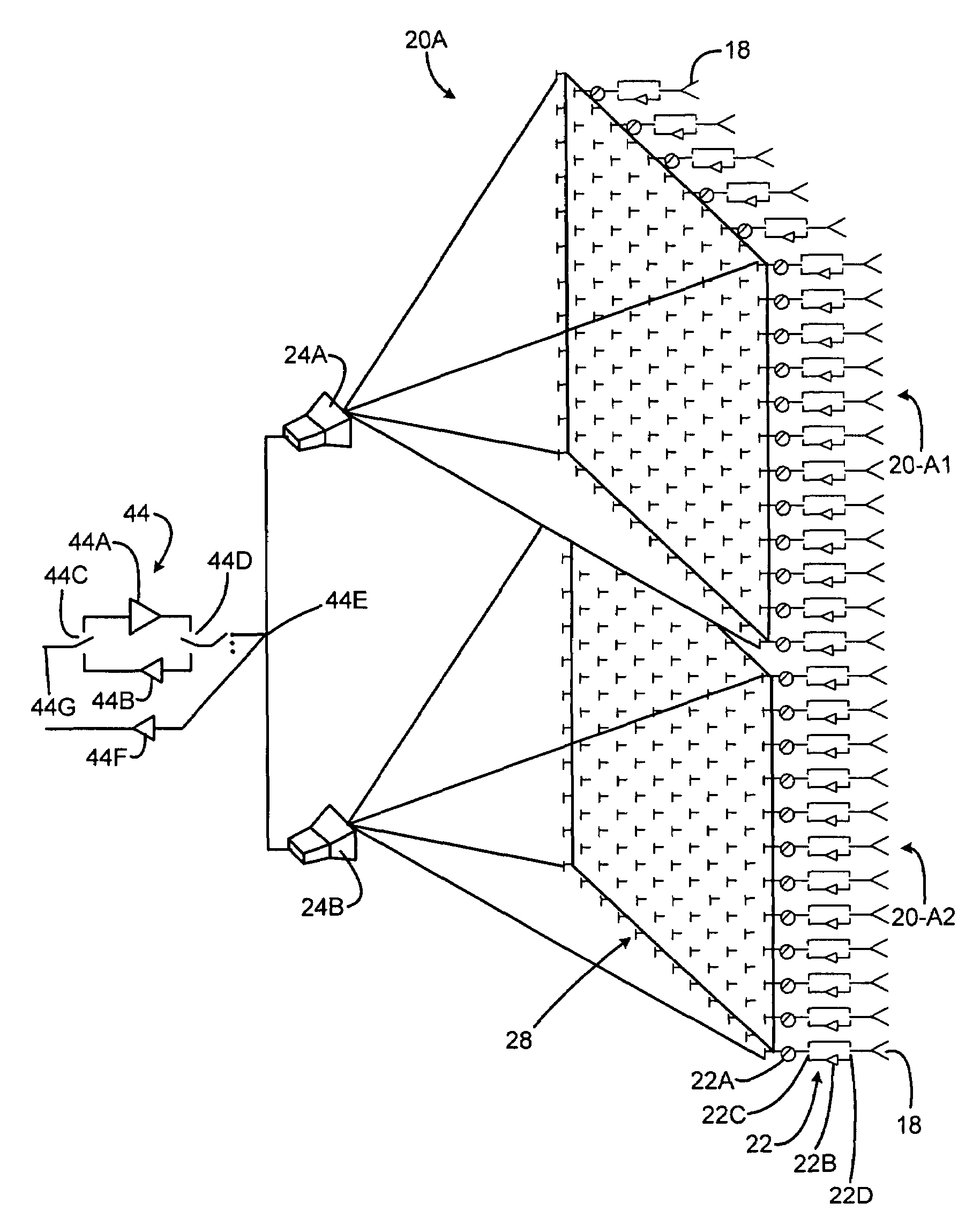
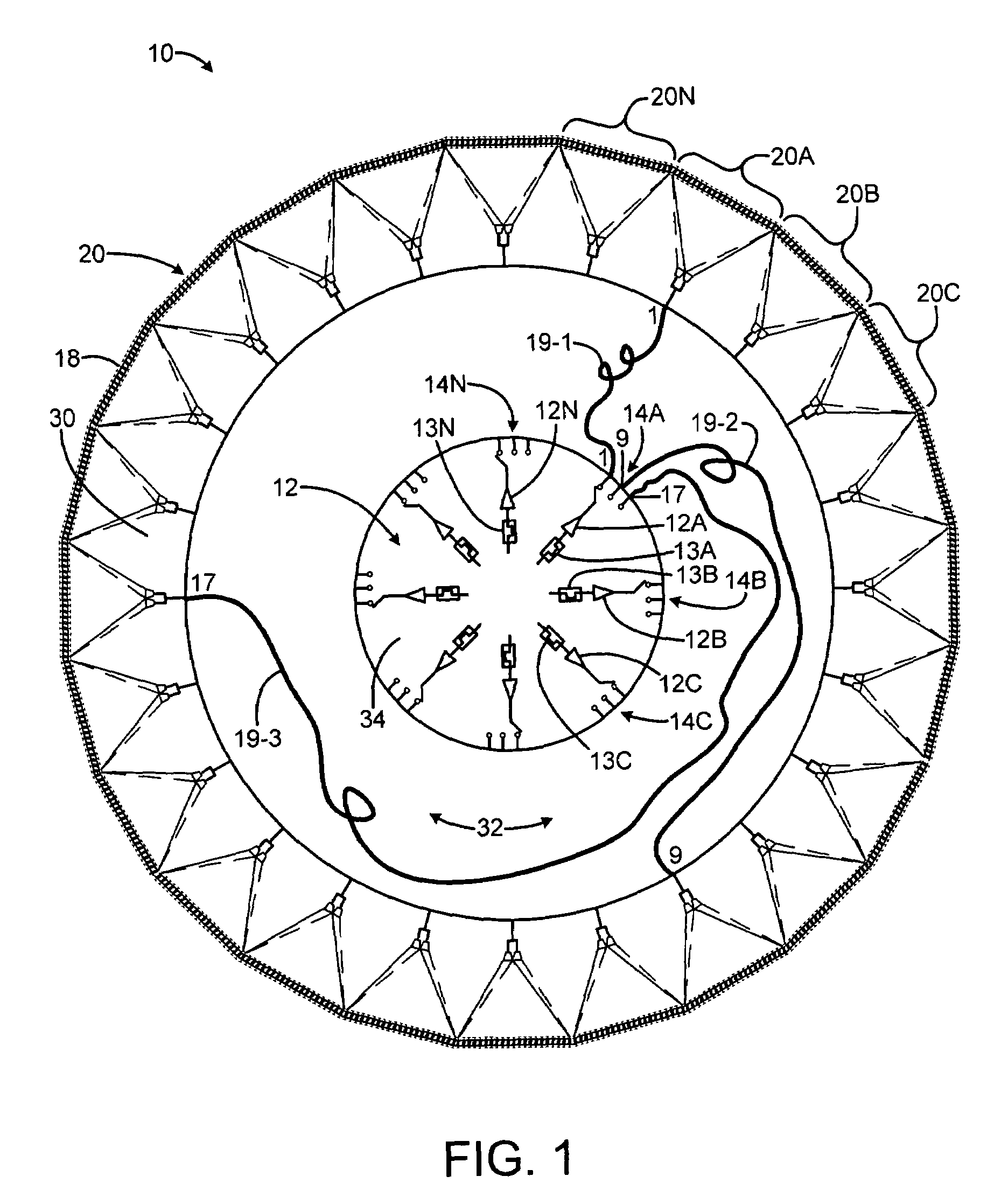
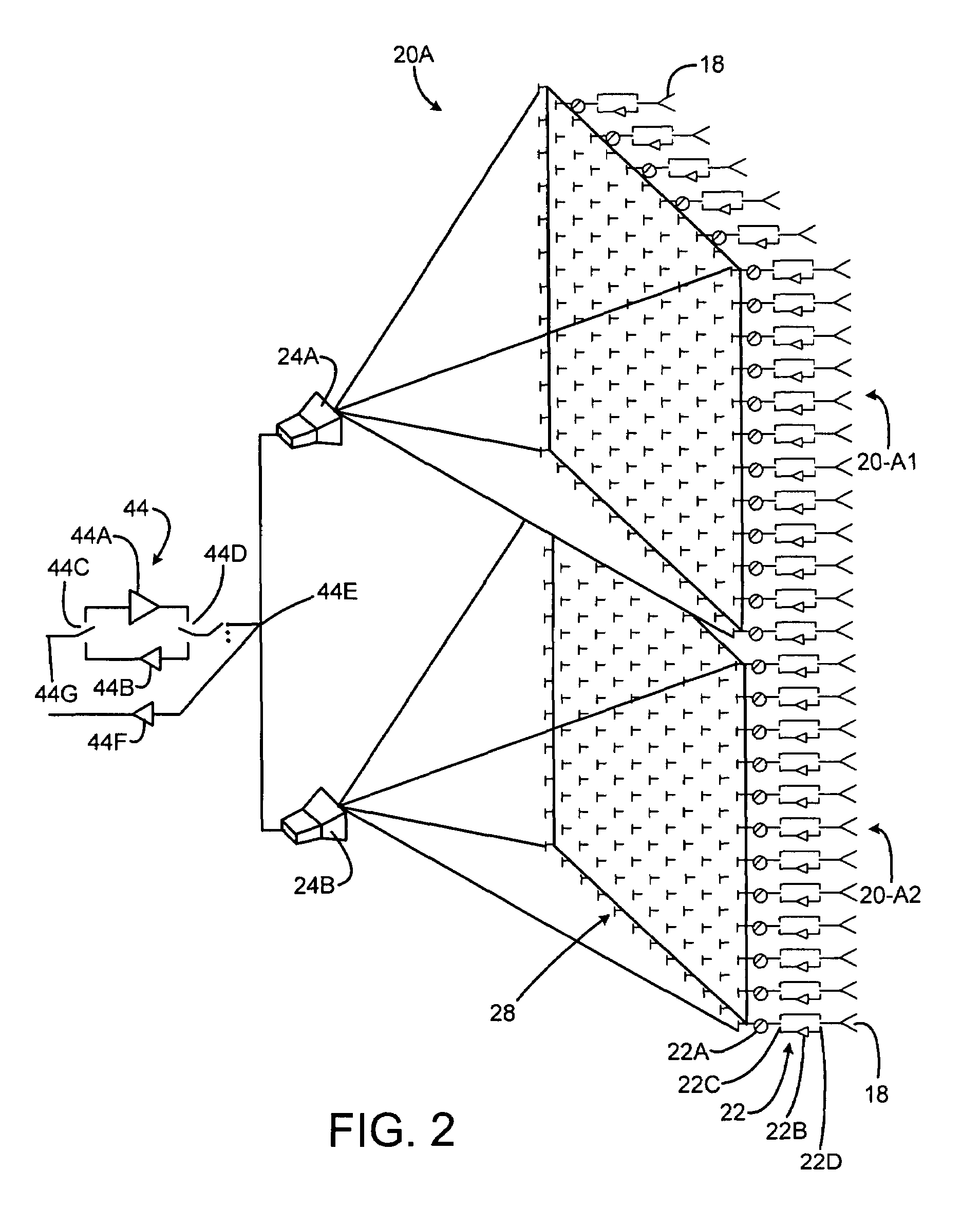
[0011]FIG. 1 is a top view of an exemplary embodiment of an antenna array 10. The exemplary array embodiment may include a central bank 12 of high power amplifiers (HPAs) 12A, 12B, 12C . . . 12N which can be switched on a beam-to-beam basis to illuminate a desired sector. Switches 14A-14N may form a commutating switch matrix for this purpose. Radiating elements 18 are disposed about the periphery of the array aperture, e.g. in this case in a generally circula...


PUM


Abstract

An electronically scanned antenna may include a plurality of space-fed, contiguous subarrays arranged in an annular region, each subarray including an inner set of radiating elements facing inwardly, an outer-facing set of radiating elements, and a feed system for illuminating the inner set of radiating elements. A plurality of RF amplifiers are coupled through a commutation switch matrix to selected ones of the subarray feed horn systems to illuminate a desired sector with RF energy.

Description

BACKGROUND[0001]Most conventional phased arrays use corporate feeds to distribute transmit (Tx) power to the radiating elements. However, for a high power large circular array, the corporate feed network would be complex, lossy, and costly to build.SUMMARY OF THE DISCLOSURE[0002]An electronically scanned antenna includes a plurality of space-fed, contiguous subarrays arranged in an annular region. Each subarray includes an inner set of radiating elements facing inwardly, an outer-facing set of radiating elements, and a feed horn system for illuminating the inner set of radiating elements. A plurality of high power RF amplifiers are coupled through a commutation switch matrix to selected ones of the subarray feed horn systems to illuminate a desired sector with RF energy.BRIEF DESCRIPTION OF THE DRAWINGS[0003]FIG. 1 is a simplified schematic diagram of an exemplary embodiment of an antenna aperture.[0004]FIG. 2 is a schematic diagram illustrating an exemplary embodiment of a single s...

Claims


Application Information

Patent Timeline
IPC IPC(8): H01Q3/00
CPCH01Q1/28H01Q3/242H01Q3/36H01Q21/0018H01Q21/205
Inventor GARFINKLE, ROBERT J.WHEELER, JOSEPH E.WELLS, DONALD R.LEE, JAR J.RITCH, RICHARD P.
Owner RAYTHEON CO
Why Eureka
Try Eureka