Light source lens

a light source and lens technology, applied in the field of light source lenses, can solve the problems of poor sight and sore eyes, and achieve the effect of avoiding sore eyes and poor sight, and soft lighting

Inactive Publication Date: 2009-01-13
OPTRON OPTOELECTRONICS CORP
View PDF5 Cites 4 Cited by
  • Summary
  • Abstract
  • Description
  • Claims
  • Application Information

AI Technical Summary

Benefits of technology

[0003]A primary object of the present invention is to provide a light source lens that may be applied on an LED lamp to eliminate the halo formed around an illuminated area, and concentrate the light source while creating a softer lighting effect to avoid sore eyes and poor sight.
[0004]To achieve the above and other objects, the light source lens according to the present invention includes a circular lens mount and a lens. The circular lens mount is provided along an outer periphery with an upright flange having a predetermined height to define a shallow concave recess on the annular lens mount. A top surface of the shallow concave recess is reflectorized, and a square opening is formed at a center of the shallow concave recess to allow a light source to project therethrough. The lens is engaged with the lens mount to locate above the shallow concave recess to receive the light source projected thereto via the square opening, and includes a first spherical portion and a second spherical portion slightly raised from a top center of the first spherical portion, so that the first and the second spherical portion diffuses and concentrates, respectively, the light source passed through the lens to eliminate any halo from an illuminated area.
[0005]In the present invention, the lens is densely provided at a bottom with a plurality of irregular grooves to form an uneven bottom surface. The uneven bottom surface of the lens causes the light source passed therethrough to scatter at more different angles, so that a softer lighting effect is created.

Problems solved by technology

The light source passed through the conventional lens is not soft enough to thereby easily cause sore eyes when a user works under the LED lamp over a long time.
The sharp light also tends to result in poor sight.

Method used


Image

  • Light source lens
  • Light source lens
  • Light source lens

Examples


Embodiment Construction

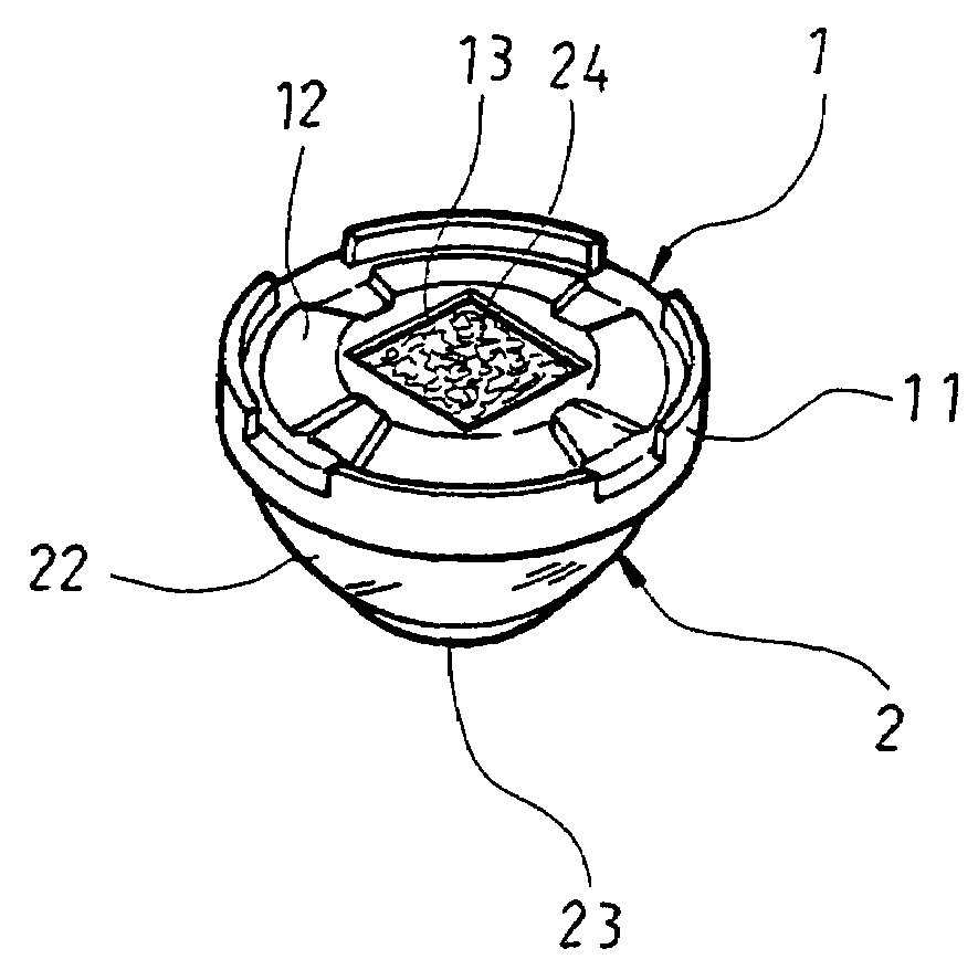
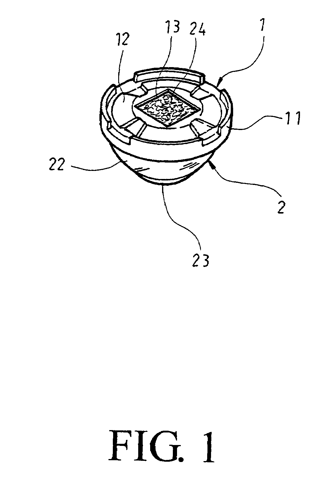
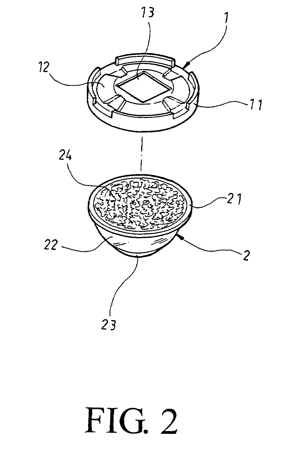
[0013]Please refer to FIGS. 1 and 2 that are assembled and exploded bottom perspective views, respectively, of a light source lens 100 according to a preferred embodiment of the present invention. As shown, the light source lens 100 of the present invention includes a circular lens mount 1 and a lens 2.

[0014]The circular lens mount 1 is provided along an outer periphery with an upright flange 11 having a predetermined height, so that a shallow concave recess 12 is defined on the annular lens mount 1 within the flange 11. A top surface of the shallow concave recess 12 is reflectorized, and a square opening 13 is formed at a center of the shallow concave recess 12 to allow a light source to project to the lens 2 via the square opening 13. The lens 2 is engaged with the lens mount 1 to locate above the shallow concave recess 12.

[0015]The lens 2 is provided around a bottom periphery with a radially extended flange 21 for firmly engaging with an inner side of the upright flange 11 on the...


PUM


Abstract

A light source lens includes a circular lens mount defining a shallow concave recess with a square opening, and a lens engaged with the lens mount to locate above the concave recess to receive light projected thereto via the square opening. The lens includes a first spherical portion and a second spherical portion protruded from a top center of the first spherical portion, and is densely provided at a bottom with a plurality of irregular grooves to form an uneven bottom surface. The first and the second spherical portion diffuses and concentrates, respectively, a light source passed through the lens, and the uneven bottom surface of the lens causes the light passed therethrough to scatter at more different angles, so that any halo is eliminated and a softer lighting effect is created.

Description

FIELD OF THE INVENTION[0001]The present invention relates to a light source lens, and more particularly to a light source lens that concentrates a light source while creating a softer lighting effect.BACKGROUND OF THE INVENTION[0002]For the light source from a light-emitting diode (LED) to be well diffused, a general LED lamp usually includes a lens disposed in front of the LED, so that the light source from the LED is projected through and refracted by the lens to form an illuminated area at a desired location. A conventional lens for this purpose has only one concave surface. Therefore, the light source passed through the lens is diffused at a uniform angle, and a significant halo is formed around the illuminated area. The light source passed through the conventional lens is not soft enough to thereby easily cause sore eyes when a user works under the LED lamp over a long time. The sharp light also tends to result in poor sight. It is therefore tried by the inventor to develop an ...

Claims


Application Information

Patent Timeline
Patent Type & Authority Patents(United States)
IPC IPC(8): F21V3/00
CPCF21S6/003F21V5/048F21V13/04F21V29/004F21Y2101/02Y10S362/80F21Y2115/10F21V29/74
Inventor LIN, CHUNG YIUCHEN, YUNG TAI
Owner OPTRON OPTOELECTRONICS CORP
Why Eureka
Try Eureka