Connector

a technology of connecting rods and connecting rods, applied in the direction of coupling device connections, securing/insulating coupling contact members, electrical devices, etc., can solve the problem of the locked state not being seen from the outside, and achieve the effect of preventing the resilient deformation of the lock, preventing the deformation of the lance housing, and increasing the force for locking the lance housing

Inactive Publication Date: 2009-01-13
SUMITOMO WIRING SYST LTD
View PDF8 Cites 14 Cited by
  • Summary
  • Abstract
  • Description
  • Claims
  • Application Information

AI Technical Summary

Benefits of technology

[0009]The lock of the lance housing is engaged with the interlocking portion of the housing main body while being resiliently deformed. The deformation space for the lock is exposed to the front in this assembled state. Thus, the open state of the deformation space easily can be confirmed visually from the front. The deformation space is widely open if the lock is engaged properly with the interlocking portion, whereas the deformation space is closed if the lock is engaged incompletely. In this way, the open area of the deformation space differs depending on the engaged state of the lock and an operator can easily visually identify such a state.
[0011]At least one retainer preferably is mountable into or onto the lance housing from the front and includes at least one unlock preventing piece for preventing the resilient deformation of the lock by entering the deformation space. Accordingly, a force for locking the lance housing can be increased. Further, the lock remains resiliently deformed if the lance housing is assembled incompletely. As a result, the unlock preventing piece contacts the lock, making it impossible to mount the retainer any further. The incompletely assembled state of the lance housing also can be detected by the feeling at this time. Alternatively, strong pushing forces on the retainer can push the incompletely assembled lance housing to a proper assembled position due to the abutting engagement of the unlock preventing piece with the lock.
[0012]The retainer preferably has at least one lance restricting piece for entering a deformation space for the lance and preventing deformation of the lance when the retainer is mounted into the lance housing. Accordingly, the retainer can prevent deformations of both the lock and the lance to reduce the number of parts and to simplify the construction of the entire connector.
[0014]The unlock preventing piece preferably enters the deformation space for the lock when the retainer is at the first position, but the lance restricting piece is not in the deformation space for the lance. Thus, the terminal fitting can be inserted into the front and rear cavities. However, the unlock preventing piece and the lance restricting piece both are in the deformation spaces therefor when the retainer is at the second position. Accordingly, the retainer can be united with the housing in its partly locked state, and the connector can be transported, for example, to a site where the terminal fitting is inserted. In this case, the unlock preventing piece already is in the deformation space for the lock and prevents deformation of the lock. Thus, the lance housing will not separate during transportation. On the other hand, the lance restricting pieces is not yet in the deformation space for the lance when the retainer is at the first position and the lance can deform freely so that the terminal fitting can be inserted.

Problems solved by technology

Thus, there is a problem that the locked state cannot be seen from the outside at the front of the receptacle.

Method used


Image

  • Connector
  • Connector
  • Connector

Examples


Embodiment Construction

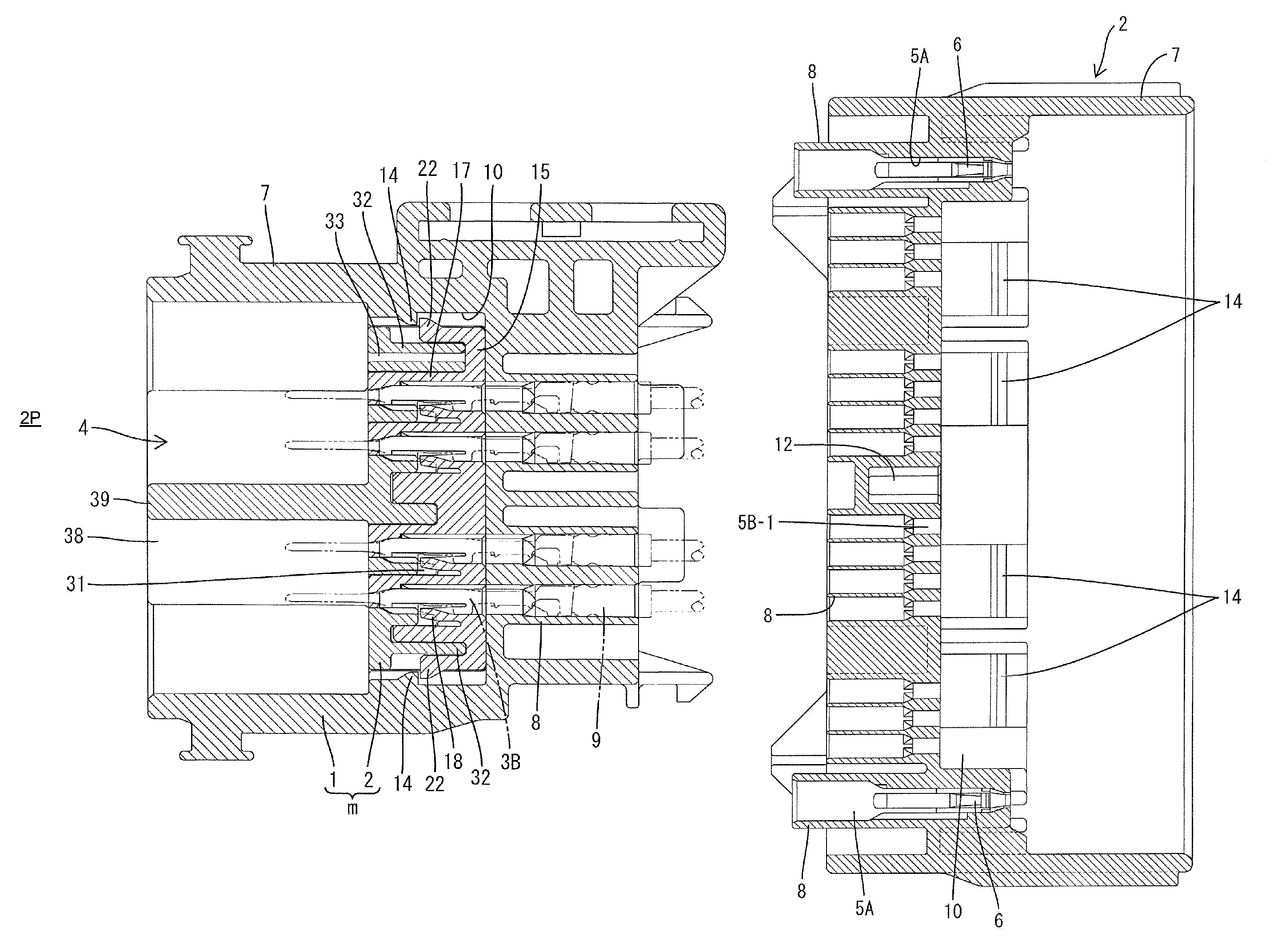
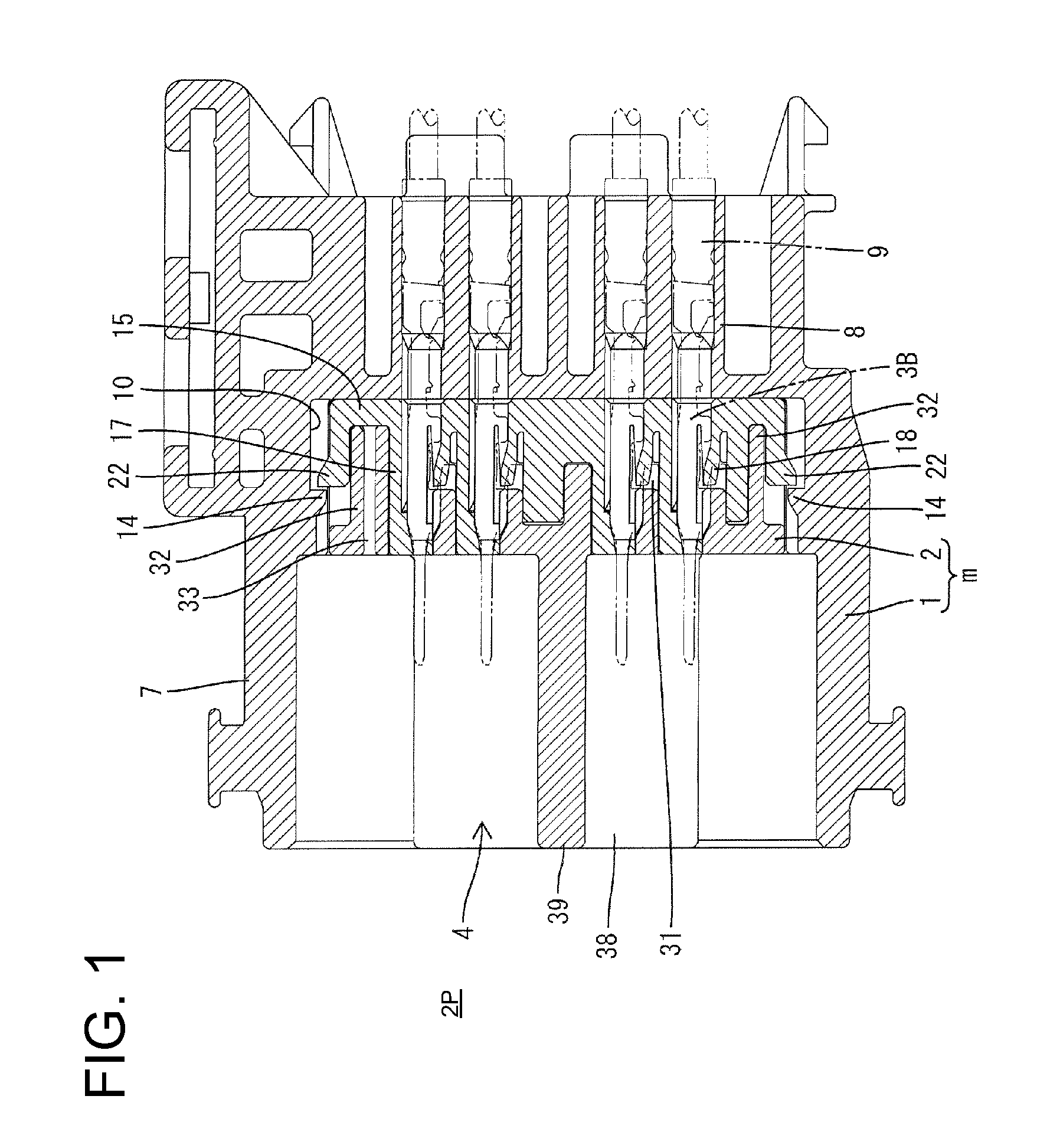
[0034]A male connector in accordance with the invention is described with reference to FIGS. 1 to 14. As shown in FIG. 1, the connector has a housing comprised of a housing main body 1 and a lance housing 2 that can be assembled with the housing main body 1. The end of the connector to be connected to a mating connector (not shown) is referred to herein as the front.

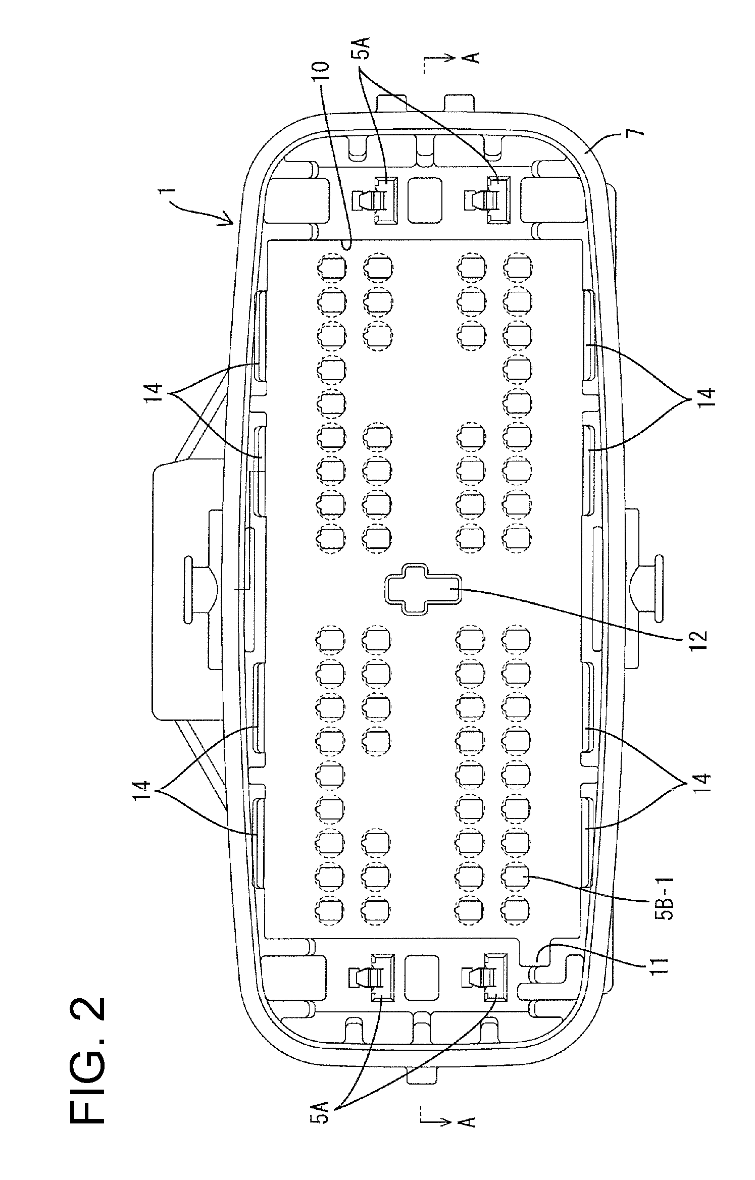
[0035]The housing main body 1 is formed unitarily e.g. of a synthetic resin. Upper and lower large cavities 5A penetrate a back side of the housing main body 1 at each of the opposite widthwise sides of the housing main body 1 for accommodating large terminals 3A. The upper and lower large cavities 5A are paired with respect to the width direction. Small cavities 5B also penetrate a back side of the housing main body 1 and are arranged substantially side by side in the width direction at each of four stages between the large cavities 5A. The small cavities 5B accommodate small terminals 3B

[0036]As shown in FIG. 1, the la...


PUM


Abstract

A housing main body (1) is formed with rear cavities (5B-1), and a lance housing (2) including locking lances (18) is formed with front cavities (5B-2). When the lance housing (2) is mounted into a mounting space (10) of the housing main body (1), locks (22) of eaves (20) are resiliently engaged with hooking claws (14) formed on wall surfaces of the mounting space (10). Since deformation spaces (21) for the eaves (20) are open at the front, if the locks (22) and the hooking claws (14) are incompletely engaged, such a state can be visually confirmed from the front side of the housing main body (1).

Description

BACKGROUND OF THE INVENTION[0001]1. Field of the Invention[0002]The invention relates to a connector.[0003]2. Description of the Related Art[0004]U.S. Pat. No. 7,001,215 discloses a connector with an inner housing and an outer housing. The outer housing of the connector includes a receptacle with an open front end, and the inner housing is fit into the outer housing from the front of the receptacle. A lock claw projects from the back wall of the inner housing and is engageable with an interlocking portion of the outer housing to fix the inner housing.[0005]The inner housing is locked at the rear of the back wall in the connector disclosed in U.S. Pat. No. 7,001,215. Thus, there is a problem that the locked state cannot be seen from the outside at the front of the receptacle.[0006]The invention was developed in view of the above situation and an object thereof is to provide a connector with a housing made up of a plurality of members, enabling easy visual confirmation of an engaged s...

Claims


Application Information

Patent Timeline
Patent Type & Authority Patents(United States)
IPC IPC(8): H01R13/514
CPCH01R13/4364H01R13/4365
Inventor TANAKA, TSUTOMUMASE, TSUYOSHI
Owner SUMITOMO WIRING SYST LTD
Why Eureka
Try Eureka