Coatings for surgical instruments

a surgical instrument and coating technology, applied in the field of coatings, can solve the problems of shortening the useful life of the instrument, spotting, staining, wear and/or damage of the surgical instrument, etc., and achieve the effect of improving the corrosion resistance of the instrument, and enhancing the corrosion resistan

Active Publication Date: 2018-11-22
DEPUY SYNTHES PROD INC
View PDF0 Cites 2 Cited by
  • Summary
  • Abstract
  • Description
  • Claims
  • Application Information

AI Technical Summary

Benefits of technology

[0007]Coated surgical instruments are described which utilize coatings to improve the corrosion-resistance and / or impart other desirable properties to the instrument (e.g., color, appearance). An uncoated surgical instrument can be formed from a variety of materials, such as varying grades of stainless steel. The instrument can be coated with one or more layers of material and / or material gradients. The composition, thickness, and technique for forming each layer can be selected to impart a specific property on the instrument, such as to improve the instrument's corrosion resistance. A corrosion-protection layer, for example, can have a higher resistance to corrosion than the untreated instrument, e.g., uncoated stainless steel. By way of example, a surgical instrument can be coated with two or more layers, such as a base layer and corrosion-protection layer / gradient. In some embodiments, the instrument can have a top layer deposited onto the corrosion-protection layer and this outer layer can have a distinctive color so that a user can more easily visually identify the instrument.
[0008]Methods for depositing coatings onto a surgical instrument are also described. Distinct coating sequences can be carried out using any combination of vapor deposition and coating systems. The methods can generally begin by pre-cleaning the uncoated / untreated instrument prior to depositing coatings or material gradients. While the techniques for coating the instrument can vary, in one example, a first vapor deposition system can be used to sequentially deposit the first metal layer and the corrosion-protection layer onto the surgical instrument and a second vapor deposition system can be used to deposit a third, outer layer onto the metal compound layer / gradient. The manufacturing methods herein can provide greater flexibility in selecting and depositing particular coatings and / or material gradients onto a surgical instrument.

Problems solved by technology

Overtime, these surgical instruments can experience wear and / or be damaged.
At the same time, the surgical instrument can be exposed to air and various bodily fluids which can cause spotting, staining, and / or corrode the instrument.
While hospitals and / or the individual physicians can reduce costs by cleaning and reusing surgical instruments, the cleaning and sterilization processes can shorten an instrument's useful life.
Stainless steel and many other metals / metal alloys are likely to corrode from normal use.
Protracted and repeated handling of a metal instrument can cause a metal instrument to corrode more quickly, as can cleaning and / or sterilization processes.
Conventional surgical instruments formed from metal are not easily identifiable because they generally have the same silver color.
However, surgical instruments are typically made from stainless steel and tend to have a similar color, making it difficult for medical personnel to quickly and easily visually identify and select the desired instrument.

Method used


Image

  • Coatings for surgical instruments
  • Coatings for surgical instruments
  • Coatings for surgical instruments

Examples


example 1

Corrosion Resistant Layer Preparation

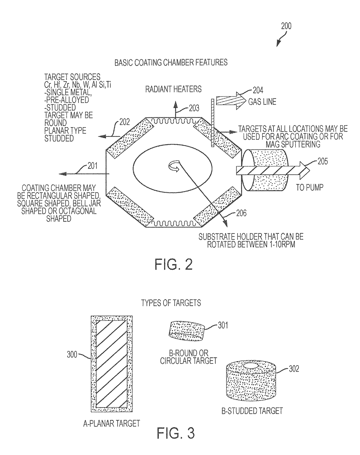
[0079]Stainless steel coupons having a CrN thin film coating (Cr first layer, CrN second layer), CrN thick film coating (Cr first layer, CrN second layer), NbO coating (Nb first layer, NbO second layer), HfO coating (Hf first layer, HfO second layer), HfN coating (Hf first layer, HfN second layer), and NbN coating (Nb first layer, NbN second layer) were prepared according to the methods described above. The CrN thin film and CrN thick film coatings (Set Nos. 1 and 3) were produced using reactive cathodic arc (RCA) technology. The NbO, HfO, HfN, and NbN coatings (Set Nos. 2 and 4-6) were produced using reactive magnetron sputtering (RPMS or suputtering) technology.

TABLE 1Six example coatings according to the invention.CrN CrN CoatingThinThickcompositionfilmfilmNbOHfNHfNNbNTechnology RCARCARPMSRPMSRPMSRPMSSet #13245617-4 NomXXXXXX17-4 LowXXXXNAX17-4 HighXXXXXX420 NomXXXXXX420 LowXXXXXX420 HighXXXXXX465 NomXXXNAXX465 LowXXXXXX465 highXXXXXX

[0080]In ...

example 2

Sample Analysis

[0081]Table 2 shows the results of sample analysis for the coating compositions shown in Table 1. The Calotte tester used a destructive tester for approximate coating thickness measurement on flat coupons (results summarized below). The Rockwell Diamler Benz test is a destructive coating adhesion / spalling test on flat coupons (results summarized below). The La wave tester is a modulus (elasticity) tester using laser induced acoustic waves (results summarized below).

[0082]The data in Table 2 shows that the advantageous properties of certain example coatings according to the invention. The HF values show generally good adhesion and spalling resistance.

TABLE 2Coupon sample analysis for the coatingcompositions shown in Table 1.La Wave onCalottoRockwell / Diamlarwitness(Si)on S304Benz Test on S304YoungsCoatingwitnessSpalling / AdhesionDensityModulusTypeThicknesslevel indicator(g / Cm3)(GPA)CrN (Thin)3.8HF-16.2320CrN (Thick)7.3HF 2-36.2218NbO3HE2-34.595HfO4.8HF-411.4131HfN3HF 1-2...

example 3

Coatings Thickness Analysis

[0083]FIGS. 5A-F illustrate example coatings and their thicknesses test results. FIG. 5A illustrates a CrN thin film having a thickness of 3.8 μm (this and other thicknesses in FIGS. 5A-F indicated and the pairs of arrows). FIG. 5B illustrates a CrN thick film having a thickness of 7.3 μm. FIG. 5C illustrates a NbO coating having a thickness of 3.0 μm. FIG. 5D illustrates a HfO coating having a thickness of 4.8 μm. FIG. 5E illustrates a HfN coating having a thickness of 3.0 μm. FIG. 5F illustrates a NbN coatings having a thickness of 3.4 μm.


PUM

PropertyMeasurementUnit
temperatureaaaaaaaaaa
thickaaaaaaaaaa
thickaaaaaaaaaa

Abstract

A coated medical instrument can include a first layer bonded to a metal substrate surface of a medical instrument, a second layer bonded to the first layer, and a third layer disposed on the second layer, The first layer comprises chromium (Cr), hafnium (Hf), titanium (Ti), and / or niobium (Nb). The second layer comprises a nitride, oxide, carbide, carbonitride, or boride of chromium (Cr), hafnium (Hf), niobium (Nb), tungsten (W), titanium (Ti), aluminum (Al), zirconium (Zr), and / or silicon (Si). The third layer comprises a nitride, oxide, carbide, boride, oxynitride, oxycarbide, or oxycarbonitride of chromium (Cr), hafnium (Hf), niobium (Nb), tungsten (W), titanium (Ti), aluminum (Al), zirconium (Zr), and / or silicon (Si). Methods for making coated medical instruments are also disclosed herein.

Description

CROSS-REFERENCE TO RELATED APPLICATIONS[0001]This application claims priority to U.S. Provisional Application No. 62 / 097,755, filed on Dec. 30, 2014 and entitled “Coating for Surgical Instruments,” which is hereby incorporated by reference in its entirety.FIELD[0002]The present application relates to coatings and methods for forming the same, for example, coatings for a surgical instrument.BACKGROUND OF THE INVENTION[0003]There are many types of surgical instruments used to perform surgical procedures in hospitals or other medical facilities. Overtime, these surgical instruments can experience wear and / or be damaged. For example, medical personnel such as doctors and nurses, often repeatedly handle a surgical instrument during a given surgical procedure. At the same time, the surgical instrument can be exposed to air and various bodily fluids which can cause spotting, staining, and / or corrode the instrument. After a surgical procedure has been completed, the instruments are typicall...

Claims


Application Information

Patent Timeline
Patent Type & Authority Applications(United States)
IPC IPC(8): C23C14/06C23C14/58C23C14/32C23C14/08C23C14/02C23C14/00A61L2/232A61L27/30A61L31/08
CPCA61L2/232A61L2420/08A61L27/306A61L31/082A61L2430/38C23C14/0641C23C14/325C23C14/022C23C14/083C23C14/0068C23C14/0089C23C14/5826
Inventor SUKADHARE, DAYANANDASELOVER, SEAN
Owner DEPUY SYNTHES PROD INC
Why Eureka
Try Eureka