System and method for commutating a motor using back electromotive force signals

a back electromotive force and signal technology, applied in the direction of dynamo-electric machines, electric variable regulation, ac motor stoppers, etc., can solve the problem of noise appearing on detected back electromotive force signals

Active Publication Date: 2009-01-13
ALLIED MOTION CANADA
View PDF49 Cites 61 Cited by
  • Summary
  • Abstract
  • Description
  • Claims
  • Application Information

AI Technical Summary

Problems solved by technology

These variations and mutual couplings tend to cause noise to appear on detected back electromotive force signals that is observed from the phase windings.

Method used


Image

  • System and method for commutating a motor using back electromotive force signals
  • System and method for commutating a motor using back electromotive force signals
  • System and method for commutating a motor using back electromotive force signals

Examples


Embodiment Construction

[0099]The description that follows, and the embodiments described therein, are provided by way of illustration of an example, or examples, of particular embodiments of the principles of the present invention. These examples are provided for the purposes of explanation, and not limitation, of those principles and of the invention. In the description, which follows, like parts are marked throughout the specification and the drawings with the same respective reference numerals.

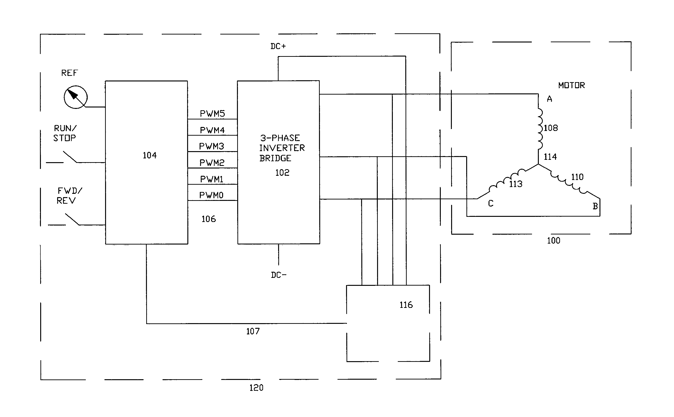
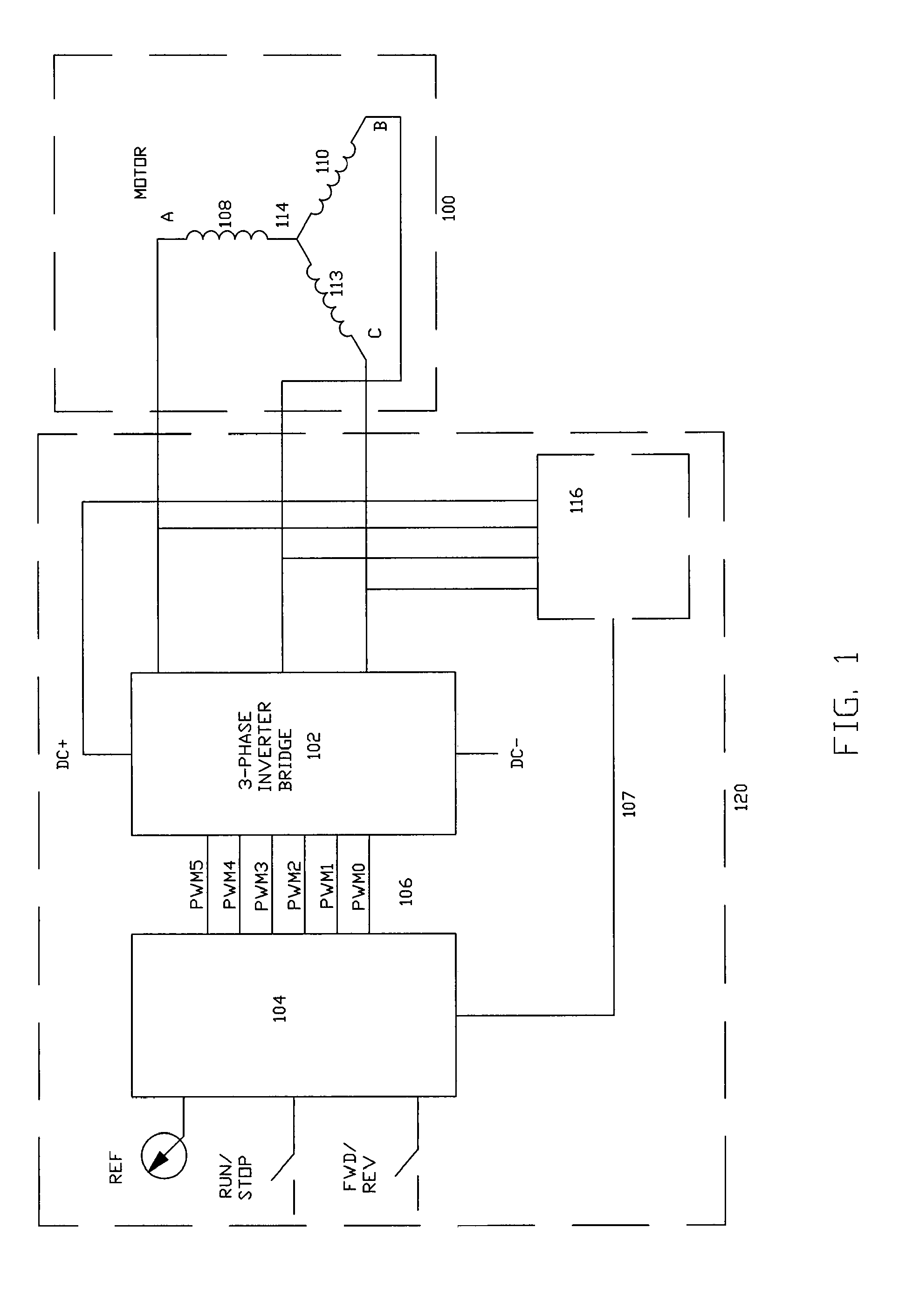
[0100]The exemplary embodiment described below makes reference to a three-phase brushless DC motor having a two-pole rotor. However, it will be appreciated by those of skill in this art that, with modifications known in the art, the present invention is applicable to other motors.

[0101]The embodiment provides several features for controlling a motor to improve its performance. Some of the features can be combined while others operate independently of the other features. Briefly, the features comprises: (1) a roto...


PUM


Abstract

A method for attenuating switching noise from back electromotive force (EMF) observations in a motor is described. The motor is controlled by pulse width modulation (PWM) signals provided at a PWM frequency. The method comprises sampling back EMF observed in the motor at a sampling frequency at least two times greater than the PWM frequency to obtain over-sampled back EMF readings. The oversampled readings may be used in a raw or filtered form to commutate the motor. A system implementing the method is also described.

Description

[0001]This is a continuation-in-part application of U.S. patent application Ser. No. 11 / 237,889 filed on Sep. 29, 2005 now U.S. Pat. No. 7,256,564.FIELD OF INVENTION[0002]The present invention relates to a system and method for handling noise associated with a back electromotive force signal in a motor, particularly a brushless DC motor.BACKGROUND OF THE INVENTION[0003]In general, permanent magnet motors, such as a polyphase brushless DC motor, have some saliency associated with them. Such saliency in a motor tend to cause self-inductance of a phase winding of the motor to arise as a function of the position of a rotor of the motor, which tends to cause mutual coupling between the energized phases of the motor and varies as a function of the position of the rotor. These variations and mutual couplings tend to cause noise to appear on detected back electromotive force signals that is observed from the phase windings.[0004]It is may therefore be advantageous to attenuate this noise to...

Claims


Application Information

Patent Timeline
Patent Type & Authority Patents(United States)
IPC IPC(8): H02K23/00
CPCH02P6/182H02P2209/07B25J9/16H02P6/18
Inventor MACKAY, DAVID KYLE
Owner ALLIED MOTION CANADA
Why Eureka
Try Eureka