Conductor cable having a high surface area

Active Publication Date: 2009-01-20
LENOVO GLOBAL TECH INT LTD
View PDF15 Cites 28 Cited by
  • Summary
  • Abstract
  • Description
  • Claims
  • Application Information

AI Technical Summary

Benefits of technology

[0009]One embodiment of the invention provides a cable comprising an electronically conducting wire with a cross-sectional shape defined by a simple closed curve having from 3 to 8 concave portions separated by an equal number of convex portions, wherein the simple closed curve has no point where the radius of curvature is less than one-sixth (⅙) of an overall radius of the wire and no point where

Problems solved by technology

As signals are being transmitted through cables at higher and higher frequencies, loss or attenuation is becoming a big problem.
However, the effect of dielectric loss in cables is minimum and skin effect dominates the loss and attenuation in cables.
However,

Method used


Image

  • Conductor cable having a high surface area
  • Conductor cable having a high surface area
  • Conductor cable having a high surface area

Examples


example 1

Sharp Angles Cause Greater Attenuation of High Frequency Signals

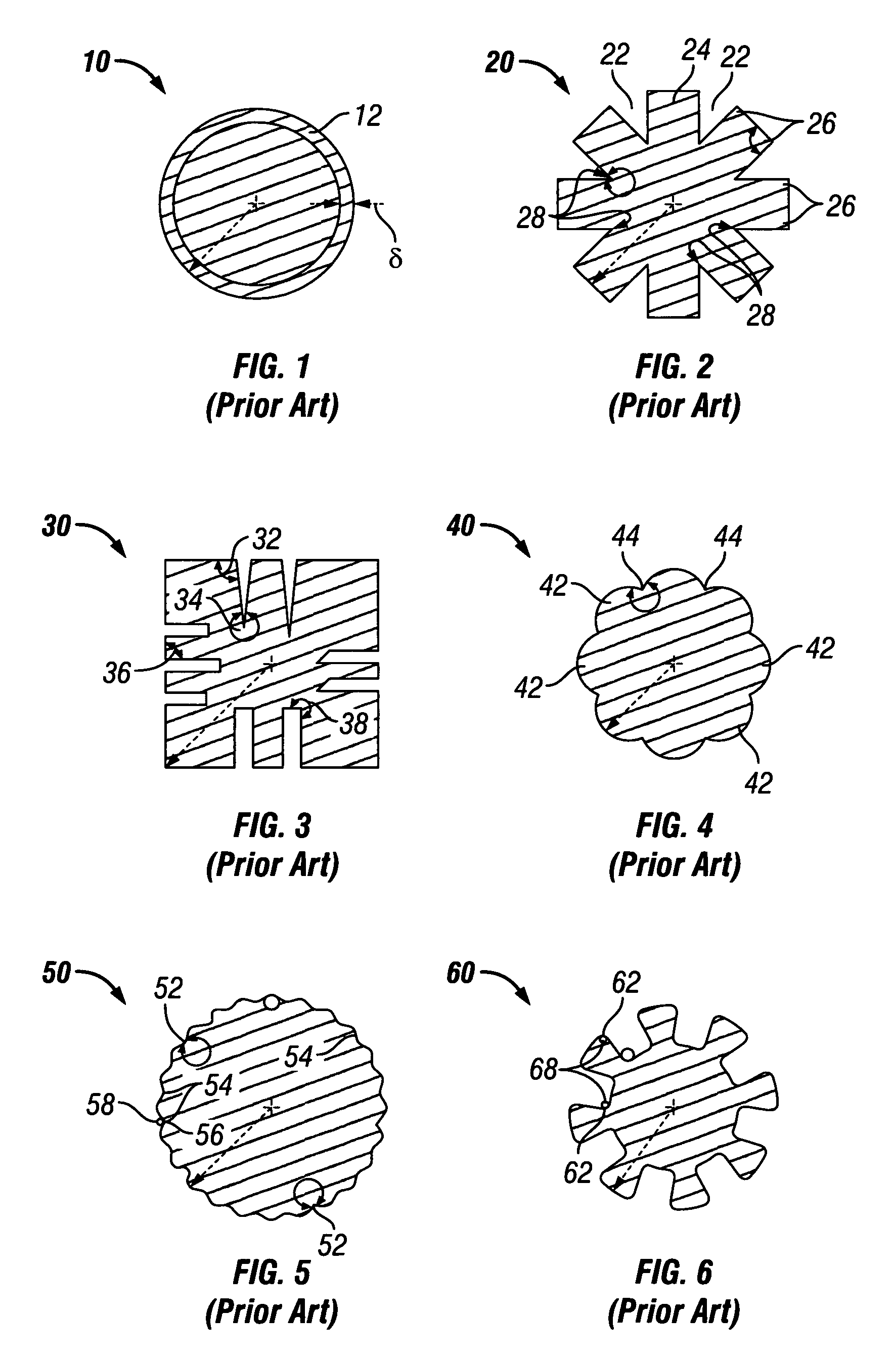
[0043]A pair of conductor cables were prepared having the same diameter and the same length (4 meters). However, a first cable had a cross-sectional shape that was round (consistent with FIG. 1) and the second cable had a cross-sectional shape that was “serrated” having a series of about eight (8) convex portions that met at a sharp angle (consistent with FIG. 4). The attenuation losses in both of these cables were measured at signal frequencies ranging from 10 MHz to 10 GHz.

[0044]FIG. 16 is a graph of the attenuation losses (dB) of the two cables that were measured as a function of signal frequency (MHz). The attenuation loss for the round cable is shown by line 160 and the attenuation loss for the serrated cable is shown by line 162. These two lines show that the round cable performed better by about 2 to 3 dB than the serrated cable at 3 GHz and 6 GHz. In general the difference in attenuation was shown to increase wi...


PUM

PropertyMeasurementUnit
Fractionaaaaaaaaaa
Radiusaaaaaaaaaa
Radiusaaaaaaaaaa

Abstract

A cable having an electrically conducting wire with a cross sectional shape defined by a simple closed curve having from three to eight concave portions separated by an equal number of convex portions. The simple closed curve has no point where the radius of curvature is less than one-sixth (⅙) of an overall radius of the wire and no point where adjacent curves or lines intersect at an angle. The alternating concave and convex portions of the cable's cross-sectional shape may have substantially the same curvature. The cross-sectional shape of the cable avoids sharp angles and fight curves.

Description

BACKGROUND OF THE INVENTION[0001]1. Field of the Invention[0002]The present invention relates to electronically conducting cable or wire having a high surface area to reduce attenuation of high frequency signal transmissions due to the skin effect.[0003]2. Description of the Related Art[0004]The main properties of a cable are its inductance, capacitance, effective shunt conductance, and series resistance per unit length. Taken together, these properties include the signal transmission and loss properties when a length of cable is employed as part of a system. As signals are being transmitted through cables at higher and higher frequencies, loss or attenuation is becoming a big problem. The two main reasons for attenuation in cables are dielectric loss and skin effect. However, the effect of dielectric loss in cables is minimum and skin effect dominates the loss and attenuation in cables.[0005]The skin effect is the tendency of an alternating electronic current (AC) to distribute its...

Claims


Application Information

Patent Timeline
IPC IPC(8): H01B7/00
CPCH01B7/0009H01B7/30
Inventor CASES, MOISESDE ARAUJO, DANIEL N.MUTNURY, BHYRAV MURTHYPHAM, NAM HUUWILKIE, BRUCE JAMES
Owner LENOVO GLOBAL TECH INT LTD
Why Eureka
Try Eureka