Cord outlet structure of electric instrument cabinet

a technology of electric instruments and cord outlets, which is applied in the direction of electrical equipment casings/cabinets/drawers, casings/cabinets/drawers details, electrical equipment, etc., can solve the problems of generating molding errors in the opening width of the opening window b>14/b> and the opening width of the cover b>2/b>, and cannot be avoided. , to achieve the effect of enhancing the safety of the electric instrumen

Inactive Publication Date: 2009-01-20
FUNAI ELECTRIC CO LTD
View PDF9 Cites 0 Cited by
  • Summary
  • Abstract
  • Description
  • Claims
  • Application Information

AI Technical Summary

Benefits of technology

[0009]However, such measures as have been described with reference to FIG. 6, that is, the provision of the projections 18a, 18b on the left and right edges 14a, 14b of the opening window 14 is effective in preventing the coin from entering through the clearance S wider than the thickness of the coin, but it is not effective in preventing the metal wire member from being inserted through the clearance S from between the projections 18a, 18b respectively provided on the two or more portions of the left and right edges 14a, 14b. When the metal wire member is inserted through the clearance S, there is a fear that such metal wire member can give rise to the short circuit of the power supply circuit. In connection with this, Japanese Utility Model Registration No 3094353 and JP-UM-A-59-87178 respectively disclose only the fact that the cover is molded integrally with the cabinet, but do not disclose measures to prevent the coin or a thin foreign body such as a metal wire member from entering through the clearance formed between the opening window and cover.
[0010]The present invention is made under the above-mentioned circumstances. That is, it is an object of the invention to provide a cord outlet structure of an electric instrument cabinet in which, in molding, a relatively wide clearance is formed between the right and left edges of an opening window of a cabinet and a cover to thereby be able to mold the cover integrally with the cabinet using only two inner and outer molds, while eliminating the need for use of the above-mentioned extra mold composed of a thin plate member; and, at the same time, when the cover is closed to the opening window to thereby shut up the opening window, generation of a clearance can be easily prevented between the left and right edges of the opening window and cover.
[0011]Also, it is another object of the invention to provide a cord outlet structure of an electric instrument cabinet which not only can accurately regulate the closing position of the cover with respect to the opening window but also, even when a metal wire member is forced into between the left and right edges of the opening window and cover, can prevent the metal wire member from being inserted into the inside of the cabinet.

Problems solved by technology

However, to mold the cabinet 1 with such dimension precision requires an extremely high level of molding technique.
In other words, even if such a dimension as to be able to prevent generation of a clearance is set in a mold design, generation of molding errors in the opening width of the opening window 14 and in the width of the cover 2 cannot be avoided due to the characteristics of resin used as the molding material and the level of the molding technique.
When the metal wire member is inserted through the clearance S, there is a fear that such metal wire member can give rise to the short circuit of the power supply circuit.
In connection with this, Japanese Utility Model Registration No 3094353 and JP-UM-A-59-87178 respectively disclose only the fact that the cover is molded integrally with the cabinet, but do not disclose measures to prevent the coin or a thin foreign body such as a metal wire member from entering through the clearance formed between the opening window and cover.
According to this structure, since the closed position of the cover closed to the opening window can be accurately regulated by the cover receiver pieces, it is possible to make it difficult for such a situation to occur that the outer surface of the cabinet and the outer surface of the cover in the periphery of the opening window are uneven and thus the external appearance of the cabinet is worsened.

Method used


Image

  • Cord outlet structure of electric instrument cabinet
  • Cord outlet structure of electric instrument cabinet
  • Cord outlet structure of electric instrument cabinet

Examples


Embodiment Construction

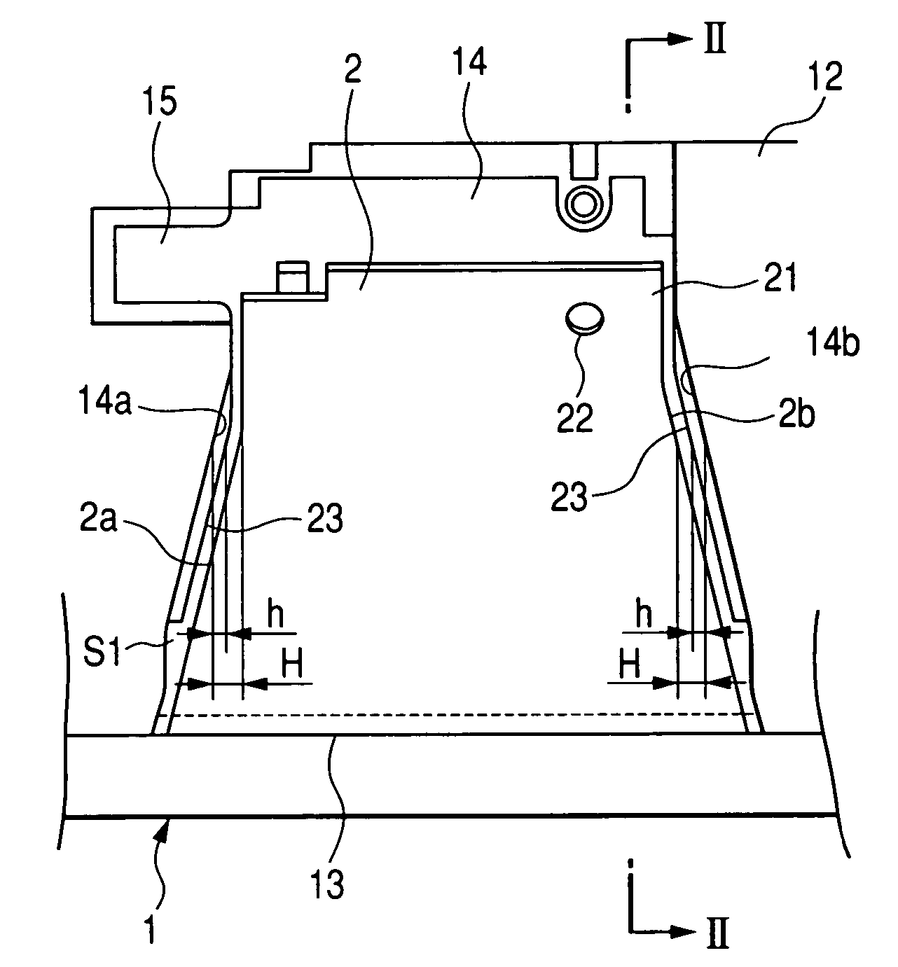
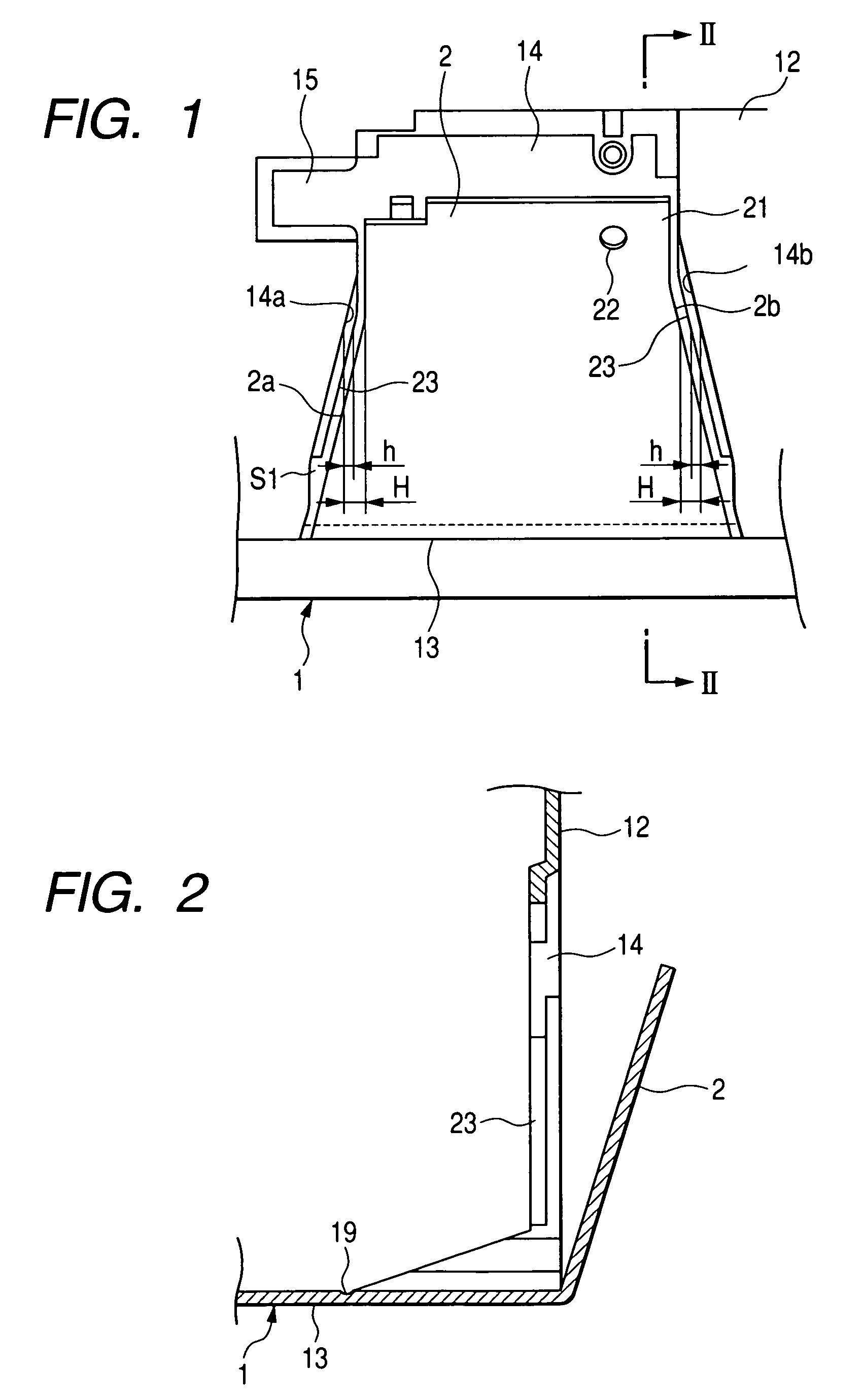
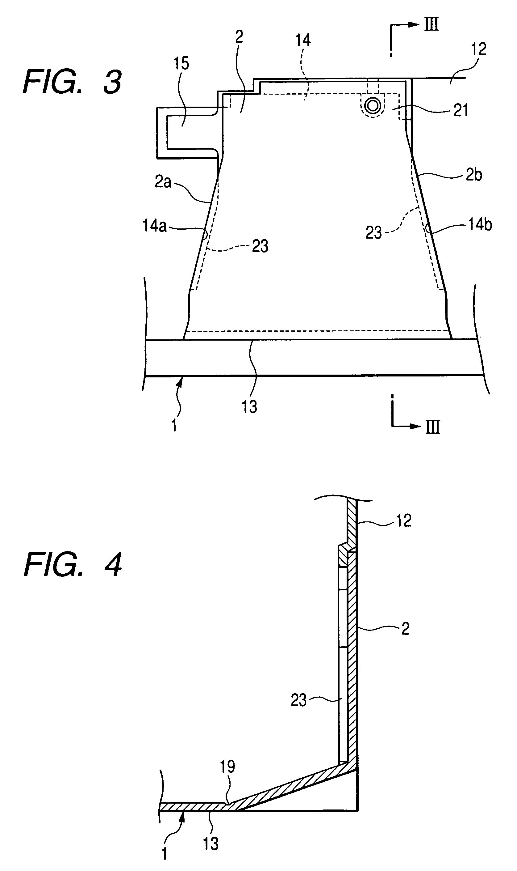
[0026]FIG. 1 is a back view of a cord outlet structure when a cabinet 1 is molded of resin and molds are then removed therefrom, FIG. 2 is a section view taken along the line II-II shown in FIG. 1, FIG. 3 is a back view of the cord outlet structure, showing a state thereof in which a cover is closed, and FIG. 4 is a section view taken along the line IV-IV shown in FIG. 3.

[0027]As a cord outlet, there is formed an opening window 14 which is opened up so as to extend over and between the back wall 12 and lower wall 13 of a cabinet 1; and, to the opening window 14, there can be closed a cover 2 which is molded of resin integrally with the cabinet 1.

[0028]As can be seen from FIG. 2 or FIG. 4, the cover 2 is continuously connected with the cabinet 1 on the lower wall 13 side of the cabinet 1 through a linear shaped resin hinge 19 composed of a thin part. Also, the whole of the cover 2 becomes smaller in width as it parts away from the resin hinge 19 except for its upper end portion 21 su...


PUM


Abstract

A cord outlet structure of an electric instrument cabinet, includes: an opening window for a cord outlet; and a cover for the opening window, wherein: the cover being formed continuous with one of the sides of the edges of the opening window through a resin hinge; the opening window is formed such that it becomes smaller in width as it parts away from the resin hinge, thereby inclining the two side edges of the opening window; the cover is formed such that it becomes smaller in width as it parts away from the resin hinge, thereby inclining both side edges of the cover; and the cover and opening window are formed such that the edges of the opening window and the side edges of the cover fitted into the opening window extend parallel to each other in their mutual adjacent positions or in their mutual contact positions.

Description

BACKGROUND[0001]1. Technical Field[0002]The present invention relates to a cord outlet structure of an electric instrument cabinet and, more specifically, the invention relates to a cord outlet structure of an electric instrument cabinet which, when the electric instrument cabinet includes not only an opening window serving as a cord outlet used to draw out power cords bound in a bundle from the inside of the cabinet to the outside thereof in the assembling process of the electric instrument or the like but also a cover molded integrally with the cabinet for closing the opening window after the cords are drawn out, can avoid generation of a clearance through which a foreign body can enter between the cover and the edge portions of the opening window when the opening window is closed by the cover.[0003]2. Related Art[0004]Conventionally, in the lower wall of a cabinet of an electric instrument, there is formed a relatively large opening window serving as a cord outlet used to draw ou...

Claims


Application Information

Patent Timeline
Patent Type & Authority Patents(United States)
IPC IPC(8): H05K5/03
CPCH02G3/083
Inventor IWAI, TAKEOMAKINO, KATSUHIKO
Owner FUNAI ELECTRIC CO LTD
Why Eureka
Try Eureka