Optical tunable filter and method of manufacturing the same
a technology manufacturing methods, applied in the field of optical tunable filters, can solve problems such as the inability to attenuate ligh
- Summary
- Abstract
- Description
- Claims
- Application Information
AI Technical Summary
Benefits of technology
Problems solved by technology
Method used
Image
Examples
first embodiment
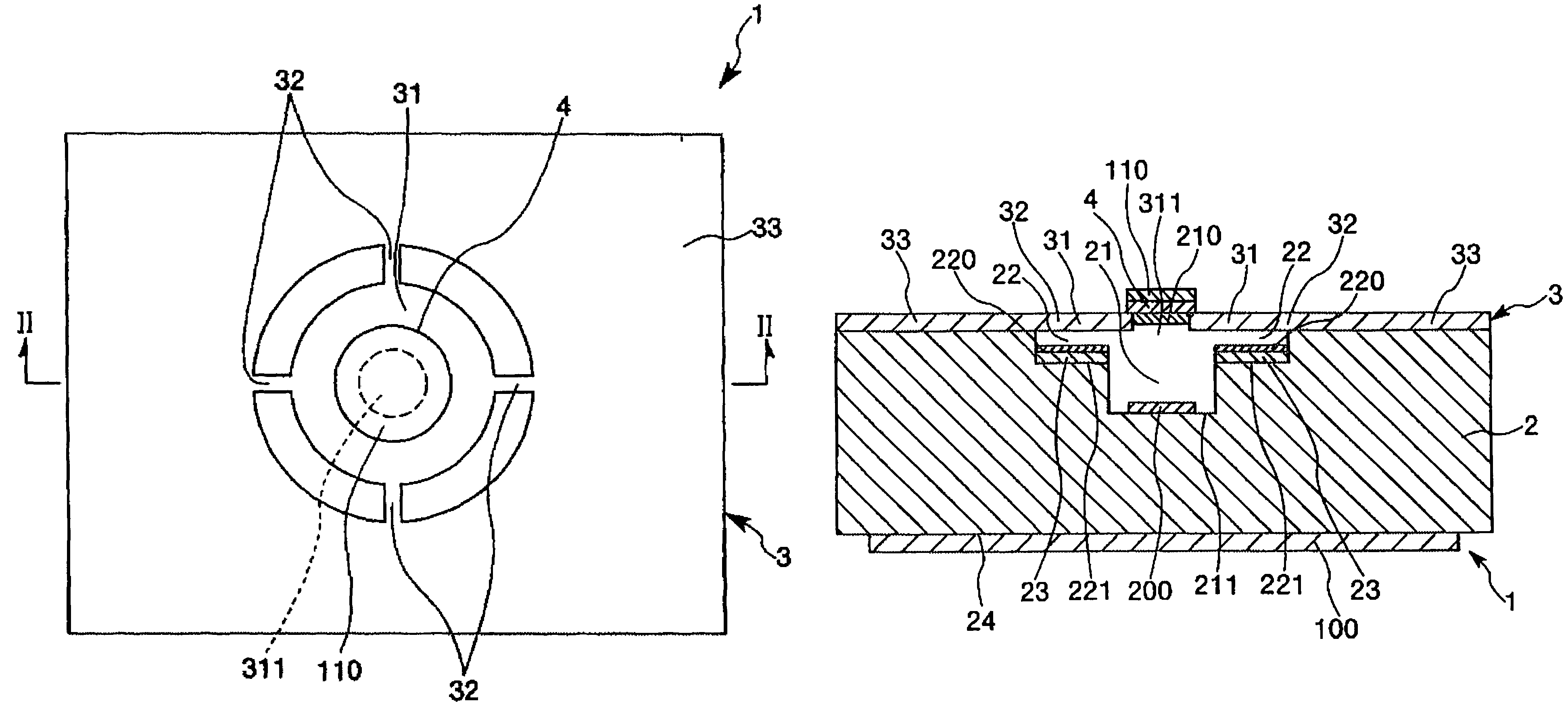
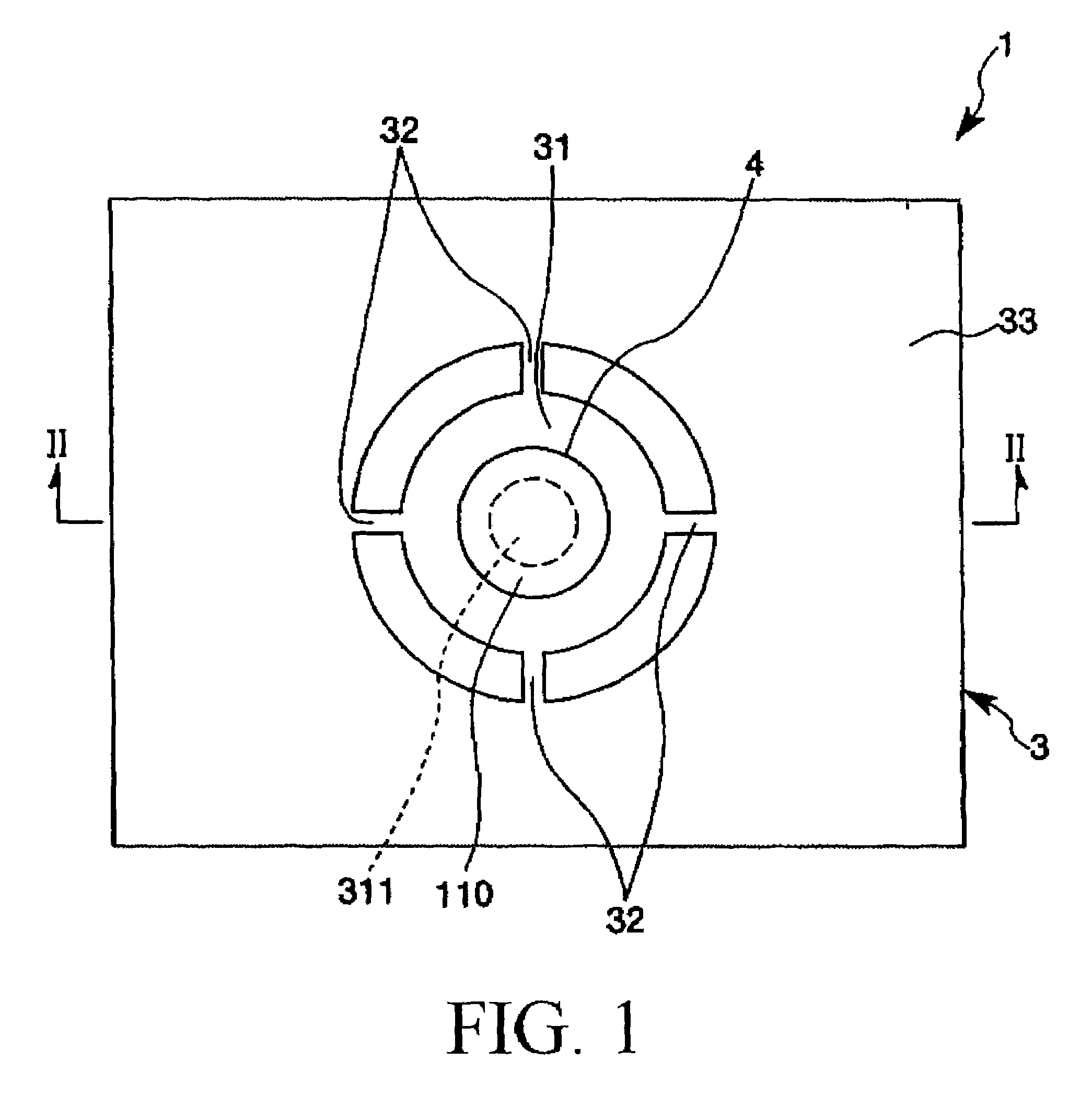
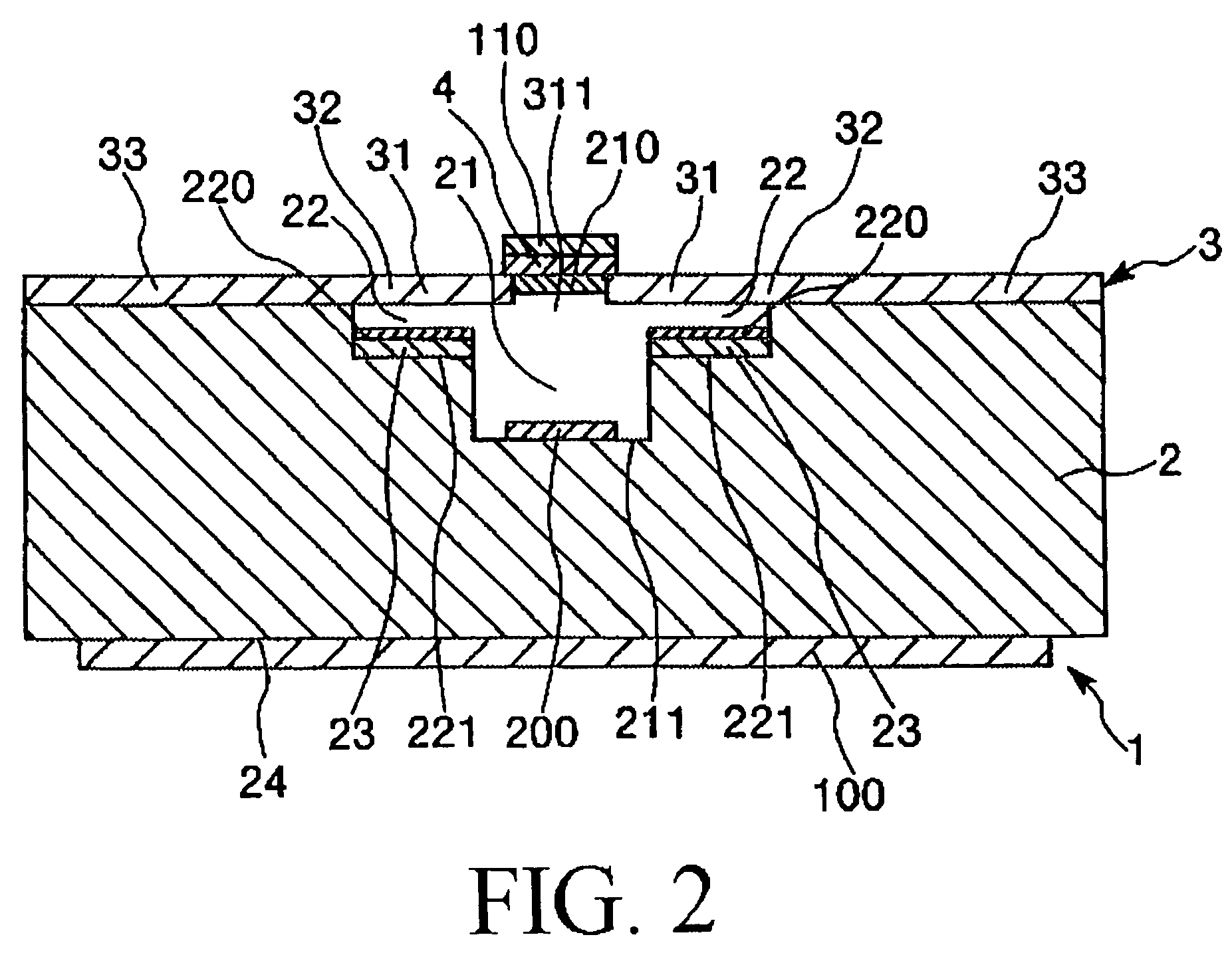
[0078]FIG. 1 is a plan view (top view) showing an optical tunable filter 1 according to a first embodiment of the present invention. FIG. 2 is a cross-sectional view taken along line II-II in FIG. 1. FIG. 3 is a diagram explanatory of an operation of the optical tunable filter 1. In the following description, upper and lower sides in FIG. 2 will be referred to as “upper” and “lower,” respectively.
[0079]For example, the optical tunable filter 1 serves as a device for receiving light and emitting light (coherent light) corresponding to a predetermined frequency. As shown in FIG. 2, the optical tunable filter 1 includes a fixed substrate 2 having a light transmittance, a movable substrate 3 facing the fixed substrate 2, a light-transmittable substrate 4 having a light transmittance, an interference gap 21, and a drive gap 22. The movable substrate 3 has an electric conductivity and a light transmittance. The interference gap 21 and the drive gap 22 are formed between the fixed substrat...
second embodiment
[0150]An optical tunable filter according to a second embodiment of the present invention will be described. FIG. 5 is a plan view (top view) showing an optical tunable filter 1001 according to the second embodiment of the present invention. FIG. 6 is a cross-sectional view taken along line VI-VI in FIG. 5. The following description of the optical tunable filter 1001 in the second embodiment is mainly focused on differences between the second embodiment and the first embodiment. Similar portions will not be described repetitively.
[0151]The optical tunable filter 1001 of the second embodiment is different from the optical tunable filter 1 of the first embodiment in that a light-transmittable substrate 4 is bonded to (provided on) a movable portion 31 at a different location than that in the first embodiment. As shown in FIGS. 5 and 6, in the optical tunable filter 1001 of the second embodiment, the light-transmittable substrate 4 is bonded to (provided on) a surface (lower surface in...
third embodiment
[0166]An optical tunable filter according to a third embodiment of the present invention will be described. FIG. 8 is a plan view (top view) showing an optical tunable filter 2001 including a movable substrate 3 and a light-transmittable substrate 4 according to the third embodiment of the present invention. FIG. 9 is a cross-sectional view taken along line IX-IX in FIG. 8. FIG. 10 is a diagram explanatory of an operation of the optical tunable filter 2001. In the following explanation, upper and lower sides in FIG. 9 will be referred to as “upper” and “lower,” respectively.
[0167]For example, the optical tunable filter 2001 serves as a device for receiving light and emitting light (coherent light) corresponding to a predetermined frequency. As shown in FIG. 9, the optical tunable filter 2001 includes a first fixed substrate 10 having a light transmittance, a movable substrate 3 facing the first fixed substrate 10, a light-transmittable substrate 4 having a light transmittance, and a...
PUM
 Abstract
Description
Claims
Application Information
 - R&D
- Intellectual Property
- Life Sciences
- Materials
- Tech Scout
- Unparalleled Data Quality
- Higher Quality Content
- 60% Fewer Hallucinations
Browse by: Latest US Patents, China's latest patents, Technical Efficacy Thesaurus, Application Domain, Technology Topic, Popular Technical Reports.
© 2025 PatSnap. All rights reserved.Legal|Privacy policy|Modern Slavery Act Transparency Statement|Sitemap|About US| Contact US: help@patsnap.com


