Deep water lift system remote pendant

Inactive Publication Date: 2009-02-03
NAVY SEC OF THE THE UNITED STATES OF AMERICA AS REPRESENTED BY THE
View PDF8 Cites 4 Cited by
  • Summary
  • Abstract
  • Description
  • Claims
  • Application Information

AI Technical Summary

Benefits of technology

[0007]The present invention provides for a system for controlling the raising and lowering of an object in water. A flotation unit is positioned above a submerged object. Hoist machinery mounted on the flotation unit has an operatively interconnected power supply, motor and winch mounting a cable for raising and lowering the object. A control pendant has a bitter and distal end, and the bitter end is coupled to the hoist machinery. The control pendant has a length to extend below and from said flotation unit to the object and has an elongate sheath defining an elongate interior extending between the bitter and distal ends. Insulated electrically conductive control lines extend the length of the elongate sheath. Each line has first and second ends, and the first end of each control line is connected to the hoist machinery. Filler material fills the remainder of the elongate interior, and a watertight control housing is connected to the elongate sheath at the distal end. A pair of switches is provided in the housing, and a separate one of the switches is each connected to a separate one of the second ends of the lines in the housing. Sealed control buttons extend from the switches and selective depression of the buttons by a diver percipient of the submerged object enables selective raising and lowering of the object.

Problems solved by technology

The increased levels of force could rupture or tear apart some relatively delicate instrumentation packages or the unwanted accelerations created by excessive force could disengage the object from the hoist line and damage it as it impacts the bottom.
Under the current salvage procedure outlined above, the hoist mechanism is not capable of being controlled in real time to provide for specifically changed forces that are tailored to avoid excessive hoisting forces and / or snapping accelerations during the extraction of the object.
Consequently, the current procedure can create hazardous conditions for personnel and machinery associated with the recovery operation.

Method used


Image

  • Deep water lift system remote pendant
  • Deep water lift system remote pendant
  • Deep water lift system remote pendant

Examples


Embodiment Construction

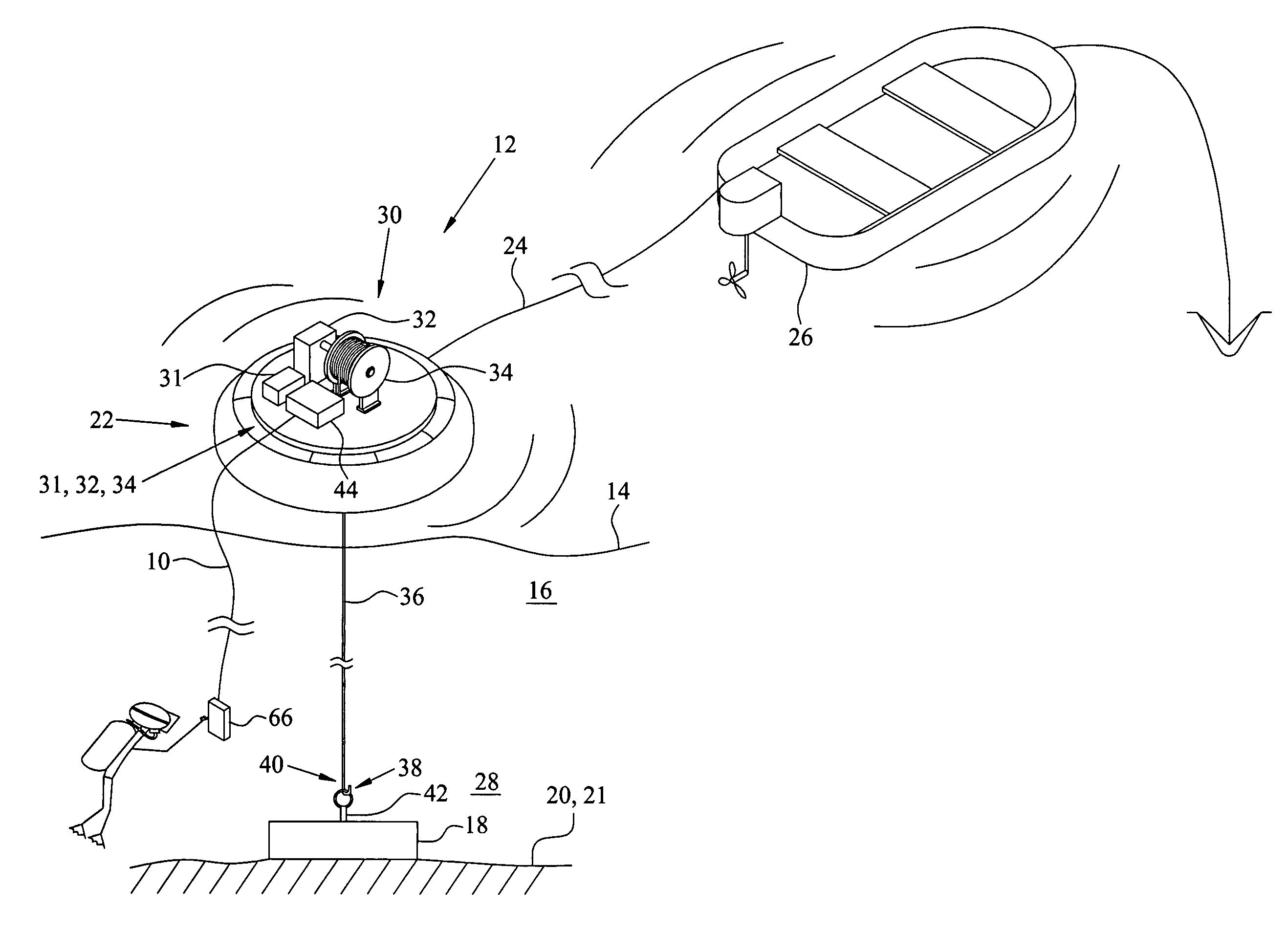
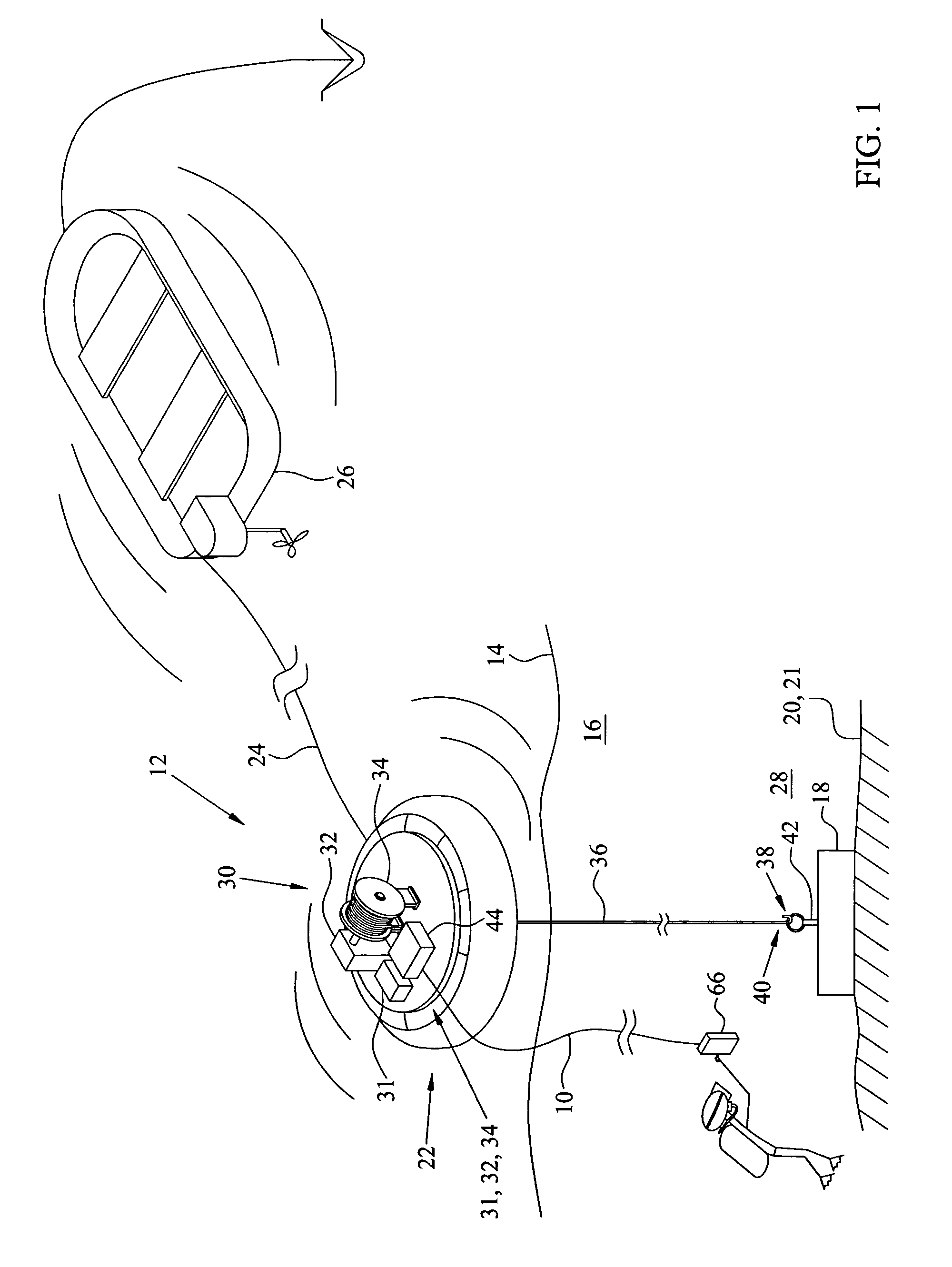
[0017]Referring to FIGS. 1 and 2, control pendant 10 of the invention extends from a deep water lift system 12 floating on the surface 14 of a body of water 16 to a submerged object 18 at the bottom 20 or in marine sediment 21 on bottom 20 or other submerged resting place. Object 18 can be, for example, an undersea instrumentation package or console adapted to gather or relay data, machinery, and / or structural members that are to be engaged and raised above bottom 20 for salvage, repair, modification, replacement, or relocated to a different site.

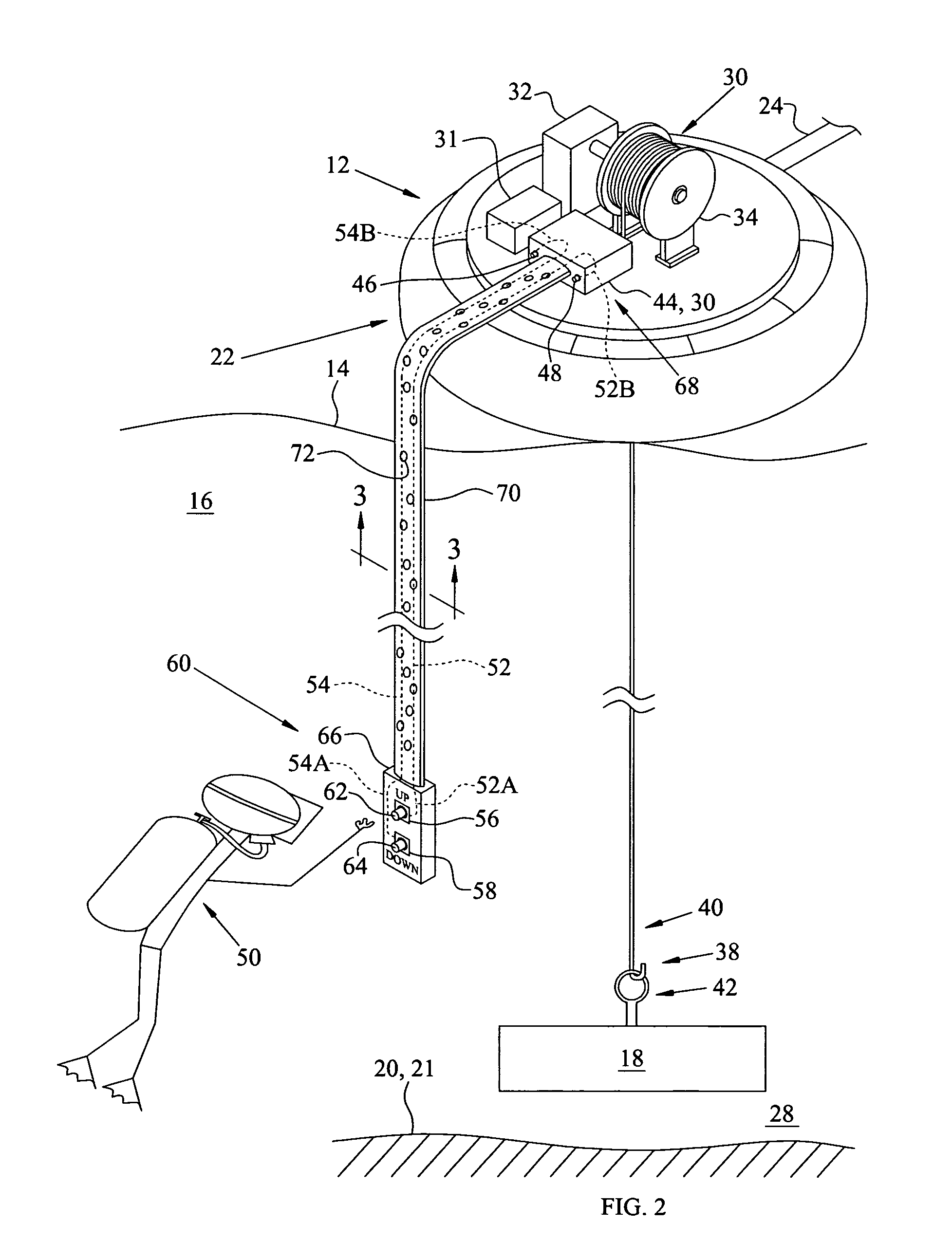
[0018]Deep water lift system 12 has a flotation unit 22 that can include reinforced, inflatable, bladder-like chambers, rigid foam-filled or hollow compartments or combinations of these components that float and provide buoyancy at surface 14. Flotation unit 22 can be self-propelled or be towed via tow line 24 by a surface craft 26 to a work site 28 where object 18 is located. Flotation unit 22 has sufficient buoyancy to support on-board ho...


PUM


Abstract

A control pendant for raising and lowering an object in water by hoist machinery allows control by a diver viewing the submerged object. The pendant has an elongate sheath defining an elongate interior extending between bitter and distal ends. The bitter end is coupled to the hoist machinery and the sheath has a length to extend below to the object. Control lines extend within the length of the elongate sheath and a first end of each control line is connected to the hoist machinery. The remainder of the sheath is filled with filler material. A watertight control housing is connected to the sheath at the distal end and contains a pair of switches that are each connected to a separate one of second ends of the lines. Sealed control buttons extend from the switches for selectively raising and lowering of said object by a percipient diver.

Description

STATEMENT OF GOVERNMENT INTEREST[0001]The invention described herein may be manufactured and used by or for the Government of the United States of America for governmental purposes without the payment of any royalties thereon or therefor.BACKGROUND OF THE INVENTION[0002]This invention relates to an apparatus for controlling a lift system for recovering submerged objects. More particularly, this invention extends from and below a buoyant lift system for controlling the raising and lowering of a submerged object by a diver within viewing distance of the submerged object.[0003]Floating structures, such as barges, pontoons and other boat-like craft have been used to support powered hoists for raising and lowering objects such as instrumentation modules, machinery, small craft, ordnance, etc., that rest on the bottom of a body of water. Hoist lines attached to the objects can bring them up to the surface zone for recovery or be used to transport them to another undersea location. The rec...

Claims


Application Information

Patent Timeline
IPC IPC(8): B63C7/00
CPCB63C7/04
Inventor BOTTOMY, CHRIS
Owner NAVY SEC OF THE THE UNITED STATES OF AMERICA AS REPRESENTED BY THE
Why Eureka
Try Eureka