Live well oxygenator

a technology of oxygenator and live well, which is applied in the field of live well oxygenator, can solve the problems of low oxygen solubility of instant patents, limited population of organisms and the size of live wells, and inability to achieve the high rate of oxygen solubility required for live wells, etc., and achieves the effect of increasing the water/oxygen contact area and accelerating the rate of oxygen solution in the water

Inactive Publication Date: 2009-02-03
STAFFORD H WAYNE
View PDF15 Cites 14 Cited by
  • Summary
  • Abstract
  • Description
  • Claims
  • Application Information

AI Technical Summary

Benefits of technology

[0011]The live well oxygenator is a vessel having walls constructed of corrosion resistant material such as plastic, high-density polyethylene, polyvinyl chloride, etc. The walls enclose a chamber, which chamber functions as a gaseous oxygen storage chamber. Suitable fittings are disposed on the walls so that gaseous oxygen may be supplied to the chamber from an outside source. The vessel is equipped with a water pump and water return pipe which are in fluid communication with the water in a live well to provide for circulation of the water through the vessel. The water pump sucks water from the live well, which water flows through pump discharge piping. The pump discharge piping is positioned in the oxygen storage chamber. An induction fitting on the discharge piping functions to induct oxygen into the water stream in finely divided bubbles. The dispersion of oxygen into tiny bubbles greatly increases the water / oxygen contact area and accelerates the rate of solution of oxygen in the water. It is estimated that the system will dissolve up to 500 percent more oxygen than water in contact with atmospheric air.

Problems solved by technology

To date, the population of the organisms and the size of the live well have been limited by the rate of oxygen that could be dissolved.
These systems are limited because of the low concentration of oxygen that can be dissolved in water from atmospheric air.
The instant patents lack the high rate of oxygen solubility required for live wells of large volume.

Method used


Image

  • Live well oxygenator
  • Live well oxygenator
  • Live well oxygenator

Examples


Embodiment Construction

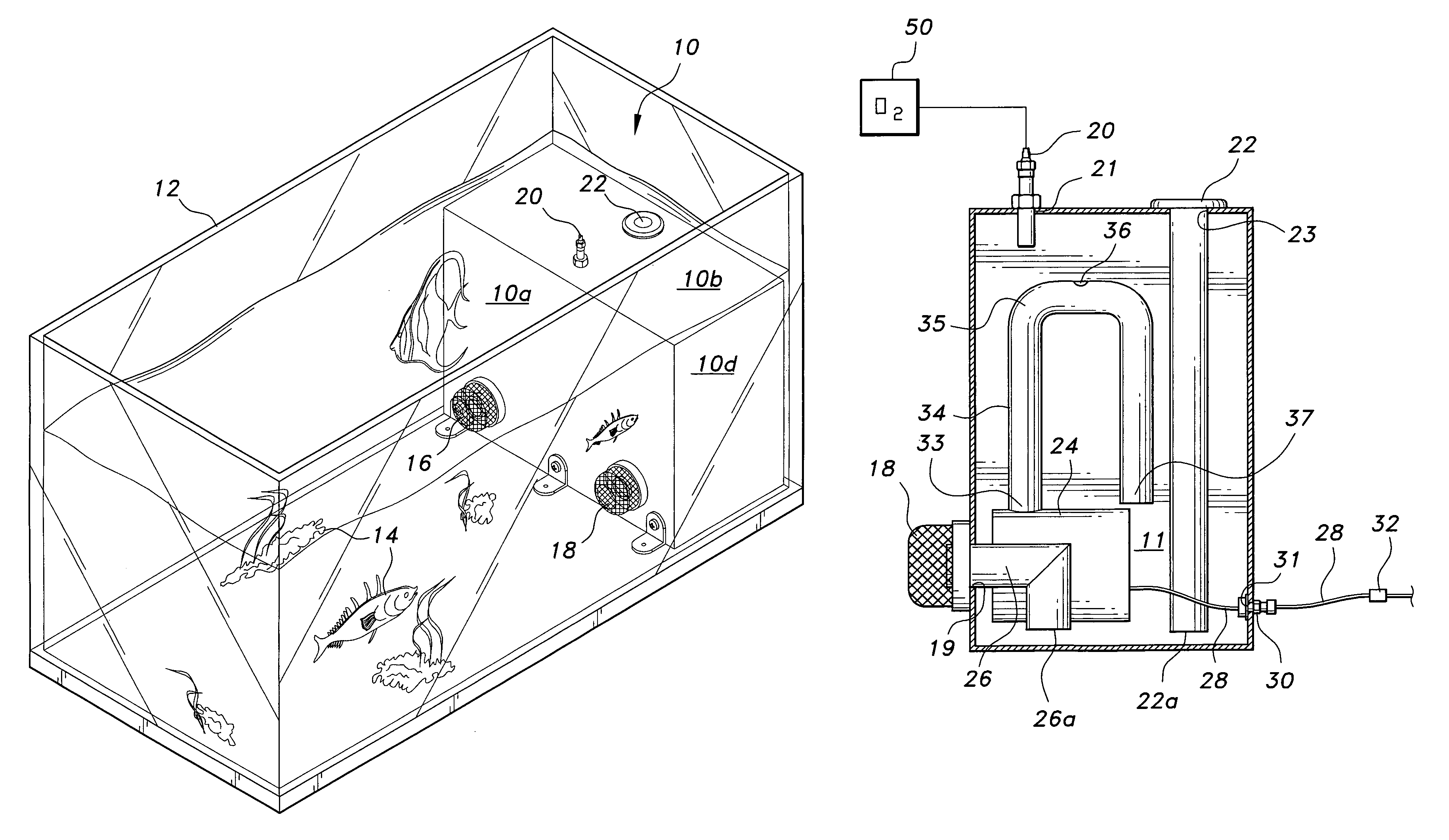
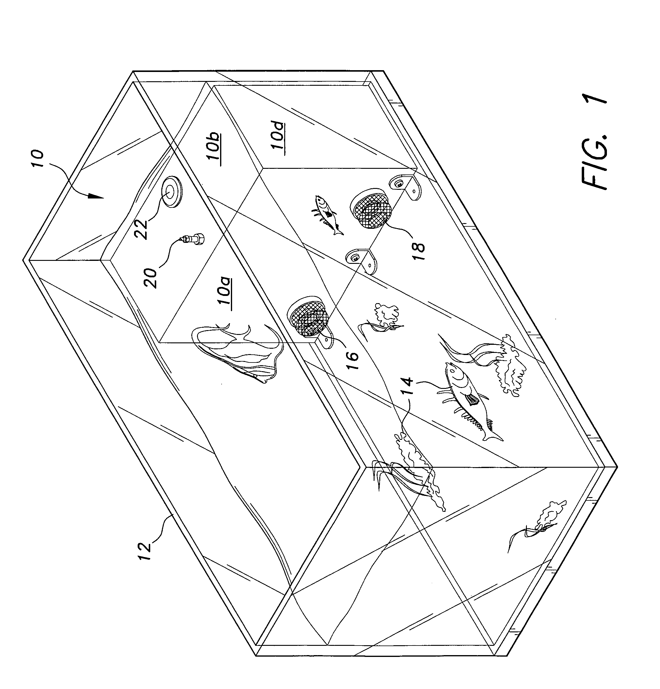
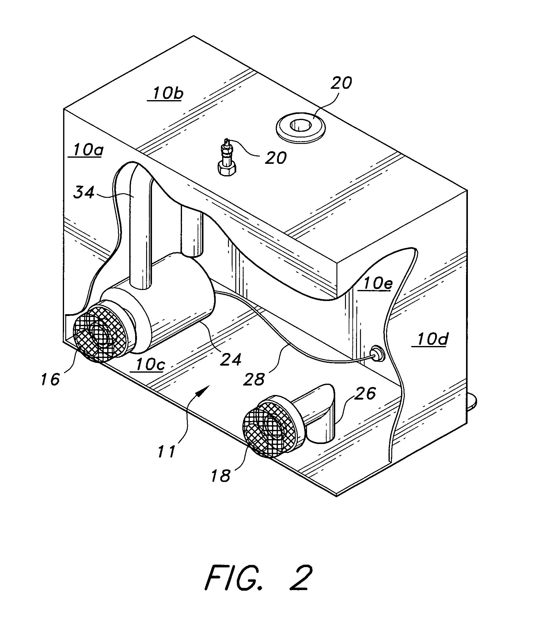
[0021]Attention is first directed to FIG. 1-4, wherein the oxygenator vessel of the present invention is generally indicated at 10. As illustrated, oxygenator vessel 10 has a front wall 10a, a top wall 10b, a rear wall 10e, a side wall 10d and 10d′ and a bottom panel 10c that enclose an inner chamber 11. As best shown in FIGS. 3 and 4, the front wall includes a first opening 17 and a second opening 19. The top wall 10b includes a third opening 21 and a fourth opening 23, and the rear wall 10e includes a fifth opening 31. Vessel 10 is positioned in a live well tank 12. Tank 12 is filled with water W, which water supports live aquatic organisms 14. First filter screen 16 is positioned over the first opening 17 and second filter screen 18 is positioned over the second opening 19 in the front wall 10a of vessel 10, whose functions will be explained below. A bleed / feed valve 20 disposed through opening 21 and overflow / fill tube 22 disposed through opening 23in the top wall 10b communicat...


PUM

PropertyMeasurementUnit
distanceaaaaaaaaaa
concentrationaaaaaaaaaa
population densitiesaaaaaaaaaa

Abstract

A live well oxygenator includes a vessel having walls constructed of corrosion resistant material. The walls enclose a chamber that functions as a gaseous oxygen storage chamber. Fittings are disposed on the walls so that gaseous oxygen may be supplied to the chamber from an outside source. The vessel is equipped with a water pump and water return pipe which are in fluid communication with the water in a live well to provide for circulation of the water through the vessel. The water pump sucks water from the live well so that it flows through pump discharge piping. The pump discharge piping is positioned in the oxygen storage chamber. An induction fitting on the discharge piping functions to induct oxygen into the water stream in finely divided bubbles.

Description

BACKGROUND OF THE INVENTION[0001]1. Field of the Invention[0002]The present invention generally relates to live well containers. More specifically, the present invention is drawn to apparatus for dissolving oxygen in a live well to maintain an adequate oxygen level required to sustain life of fish and other aquatic fauna.[0003]2. Description of the Related Art[0004]The storage, and / or transport of live fish and other live aquatic fauna and organisms require water containing an adequate amount of oxygen dissolved therein. The minimum amount of dissolved oxygen required to sustain life varies from species to species. It is known, however, that most species begin to experience stress at dissolved oxygen concentration below five (5) parts per million (ppm).[0005]Usually, when transporting or storing live fish or the like, the population densities are greatly increased over natural population densities. If the organisms are to be maintained in prime physical condition, it is essential th...

Claims


Application Information

Patent Timeline
Patent Type & Authority Patents(United States)
IPC IPC(8): A01K63/04
CPCA01K63/042A01K97/05
Inventor STAFFORD, H. WAYNE
Owner STAFFORD H WAYNE
Why Eureka
Try Eureka