Liquid droplet jetting apparatus having liquid-repellent jetting surface, nozzle plate having liquid-repellent jetting surface, and method for producing the nozzle plate

a technology of liquid-repellent jetting and liquid-repellent nozzles, which is applied in the field of liquid-repellent jetting apparatuses, liquid-repellent jetting nozzles, and methods for producing nozzles. it can solve problems such as degradation of print quality, and achieve the effect of simplifying the production process

Active Publication Date: 2009-02-03
BROTHER KOGYO KK
View PDF10 Cites 4 Cited by
  • Summary
  • Abstract
  • Description
  • Claims
  • Application Information

AI Technical Summary

Benefits of technology

[0008]An object of the present invention is to provide a liquid-droplet jetting apparatus which can maintain a satisfactory discharge stability even when the liquid from the nozzle is adhered to the liquid droplet discharge surface, and a nozzle plate which is used in the liquid droplet jetting constant, the shape of the liquid overflowed to the outside of the nozzle is axisymmetrical with respect to the central axis of the nozzle. Therefore, even when the liquid is returned to the inside of the nozzle, the meniscus of the liquid in the nozzle is axisymmetrical with respect to the central axis and thus there is no shift in the direction of discharge of the liquid droplet during the subsequent discharge of the liquid droplet. Accordingly, it is possible to stabilize discharge characteristics of the liquid droplets. In should be noted that in the present patent application, the term “first liquid repellent area surrounding the ejecting port” means that the first liquid repellent area is adjacent to the ejecting port, and that there is no another area between the ejecting port and the first liquid repellent area.
[0022]Moreover, in the method for producing the nozzle plate of the present invention, the substrate may be formed of a synthetic resin material and the nozzle forming step of forming the nozzle in the substrate may be performed after the light ray irradiating step. Accordingly, the nozzle is formed after forming the first liquid repellent area and the second liquid repellent area. Therefore, at the time of irradiating the light ray, it is not necessary to perform a treatment such as filling the nozzle with a resist or the like so that light rays do not irradiate or fall on the inner surface of the nozzle, thereby simplifying the production process.

Problems solved by technology

Due to the shift in the shape of the meniscus, the direction of discharge at the time of a subsequent ink discharge onward is wobbled and the ink is not discharged at an intended landing position, thereby causing the degradation of print quality.

Method used


Image

  • Liquid droplet jetting apparatus having liquid-repellent jetting surface, nozzle plate having liquid-repellent jetting surface, and method for producing the nozzle plate
  • Liquid droplet jetting apparatus having liquid-repellent jetting surface, nozzle plate having liquid-repellent jetting surface, and method for producing the nozzle plate
  • Liquid droplet jetting apparatus having liquid-repellent jetting surface, nozzle plate having liquid-repellent jetting surface, and method for producing the nozzle plate

Examples


first modified embodiment

[0076]As shown in FIG. 14, a liquid repellent film may not be formed at an annular area which surrounds the nozzle 50 of an ink discharge surface 290. In this case, the liquid repellent property of this annular area (corresponding to the first liquid repellent area) is equivalent to the liquid repellent property of the inner surface of the nozzle 50 and is lower than the liquid repellent property of the second liquid repellent film 72. Therefore, the ink remaining on the surface of a nozzle plate 243 when the ink is discharged from the nozzle 50 is spread over the entire annular area surrounding the nozzle 50 but is not moved to the second liquid repellent film 72. For this reason, the shape of the ink on the ink discharge surface 290 can be maintained to be circular and axisymmetrical with respect to the central axis of the nozzle 50.

second modified embodiment

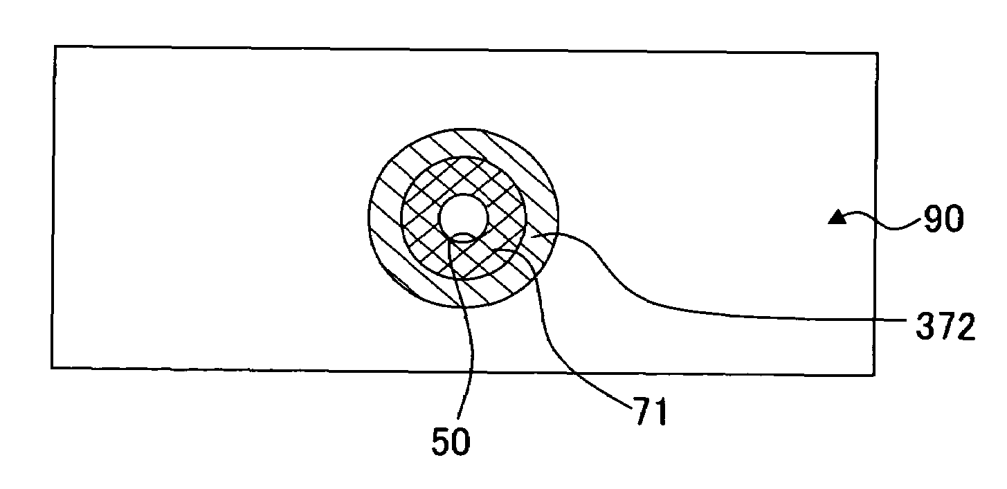
[0077]As shown in FIG. 15, a first liquid repellent film 372 which is formed on the outside of the first liquid repellent film 71 of the ink discharge surface 90 may be formed only partially (circular in this case).

third modified embodiment

[0078]In the present embodiment, the shape of the ejecting port 51 of the nozzle 50 is circular. However, the shape of the ejecting port 51 is not limited to the circular shape and may take other shape. As an example, FIG. 16A shows a nozzle 450 in which the shape of an ejecting port 451 formed in an ink discharge surface 490 is triangular. FIG. 16B shows a nozzle 550 in which the shape of an ejecting port 551 formed in an ink discharge surface 590 is rectangular.

[0079]When the shape of the ejecting port 451 is triangular as shown in FIG. 16A, the boundary between a first liquid repellent film 471 and a second liquid repellent film 472 is triangular in shape which is substantially similar to the shape of the ejecting port 451. Angles of this triangle are round and have shape of a circular arc and the center of gravity of the triangle coincides with the center of gravity of the ejecting port 451. In other words, the boundary between the first liquid repellent film 471 and the second ...


PUM


Abstract

A plurality of nozzles is formed in a nozzle plate. A first liquid repellent film which surrounds an ejecting port of each of the nozzles and which has a liquid repellent property higher than a liquid repellent property of an inner surface of the nozzle is formed on an ink discharge surface. A second liquid repellent film which has a liquid repellent property higher than the liquid repellent property of the first liquid repellent film is formed on an outer side of the first liquid repellent film. A boundary between the first liquid repellent film and the second liquid repellent film is on a circle which is concentric with a circle forming a circumference of the ejecting port of the nozzle. Discharge characteristics of liquid droplets which are discharged from the nozzle can be stabilized.

Description

BACKGROUND OF THE INVENTION[0001]1. Field of the Invention[0002]The present invention relates to a liquid droplet jetting apparatus which discharges liquid droplets, and a nozzle plate which is used in the liquid droplet jetting apparatus.[0003]2. Description of the Related Art[0004]An ink-jet head which discharges ink from nozzles onto a recording paper is available as a liquid-droplet jetting apparatus which discharges or jets liquid droplets. In this ink-jet head, pressure is applied to the ink by various kinds of actuators and the ink is discharged from the nozzles. Then, after the discharge of the ink, the ink is drawn in the nozzles because the pressure in ink channels connected to the nozzles is decreased. However, after the discharge of the ink, when the ink is not completely drawn into the nozzles and a portion or part of the ink is adhered to an ink discharge surface on which ejecting ports of the nozzles are formed, during a subsequent ink discharge, an amount of ink disc...

Claims


Application Information

Patent Timeline
Patent Type & Authority Patents(United States)
IPC IPC(8): B41J2/135
CPCB41J2/1433B41J2/1606
Inventor SUGAHARA, HIROTO
Owner BROTHER KOGYO KK
Why Eureka
Try Eureka