
Touch pad device for portable computer

a portable computer and touch pad technology, applied in the field of portable computers, can solve the problems of increased assembly man-hours, increased parts and assembly man-hours, and increased man-hours, and achieve the effect of minimizing the number of parts

Inactive Publication Date: 2009-02-03
LG ELECTRONICS INC
View PDF8 Cites 15 Cited by
  • Summary
  • Abstract
  • Description
  • Claims
  • Application Information

AI Technical Summary

Benefits of technology

Reduces assembly time and components, prevents electromagnetic wave leakage, and simplifies maintenance by integrating the touch pad housing directly onto the key deck with hooks and conductive coatings.

Problems solved by technology

First, since the touch pad housing 16 and the screws are used to allow the touch pad 13 to be fastened into the pad window 11 of the key deck 5, there are problems in that the total number of parts and the man-hours required for assembly are increased.
Further, since the touch pad housing 16 is fastened to a bottom surface of the key deck 5 with screws, there is inconvenience in that the key deck 5 must be separated from the main body 1 in order to perform maintenance on the touch pad 13.
Therefore, there is a problem in that electromagnetic (EM) waves generated in the main body 1 leak to the outside through a gap defined between the touch pad housing 16 and the bottom surface of the key deck 5.
However, this requires additional man-hours for the assembly and the production costs are increased.

Method used


Image

  • Touch pad device for portable computer
  • Touch pad device for portable computer
  • Touch pad device for portable computer

Examples


Embodiment Construction

[0034]Now, a preferred embodiment of a touch pad device of a portable computer according to the present invention will be described in detail with reference to the accompanying drawings.

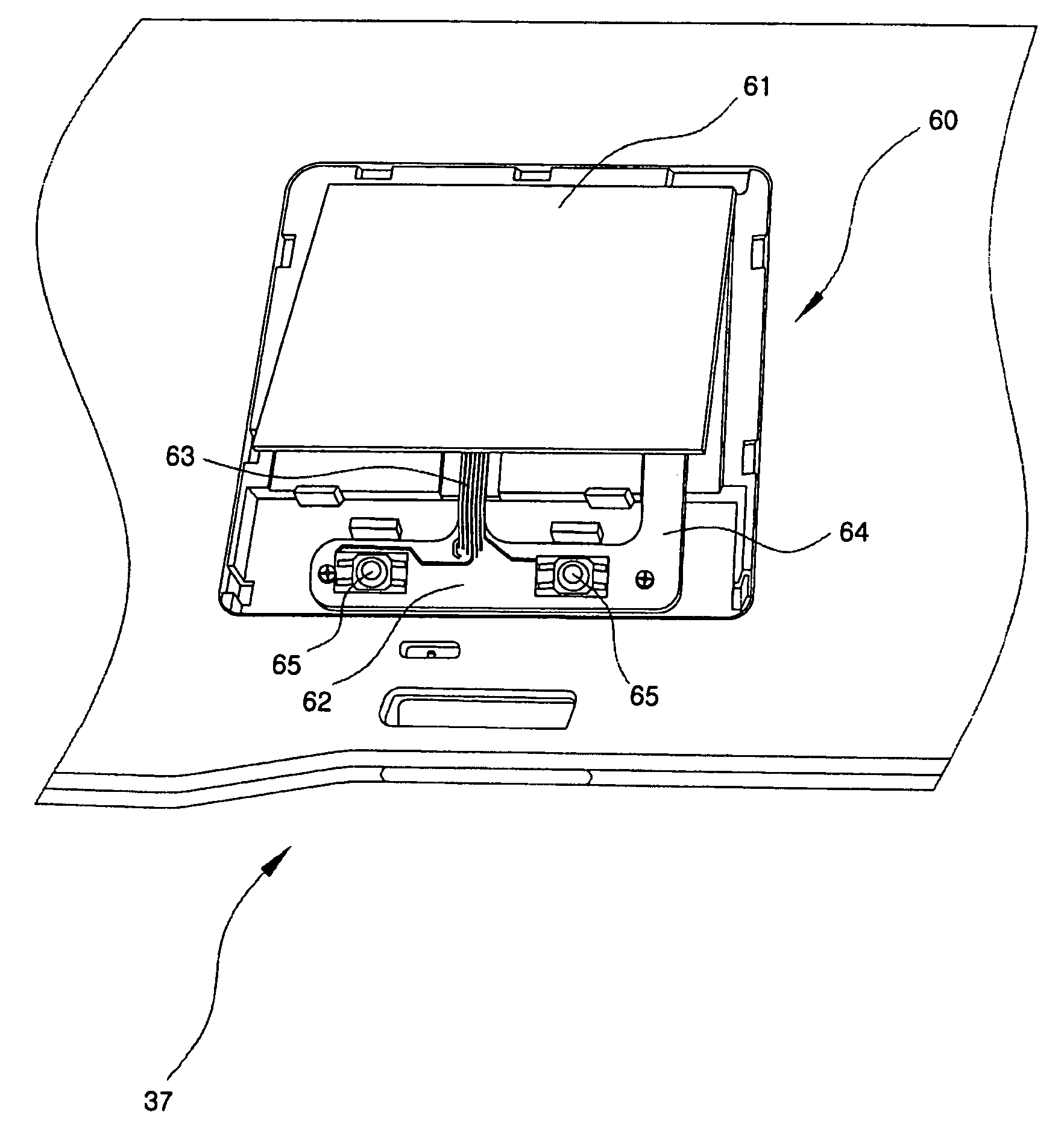
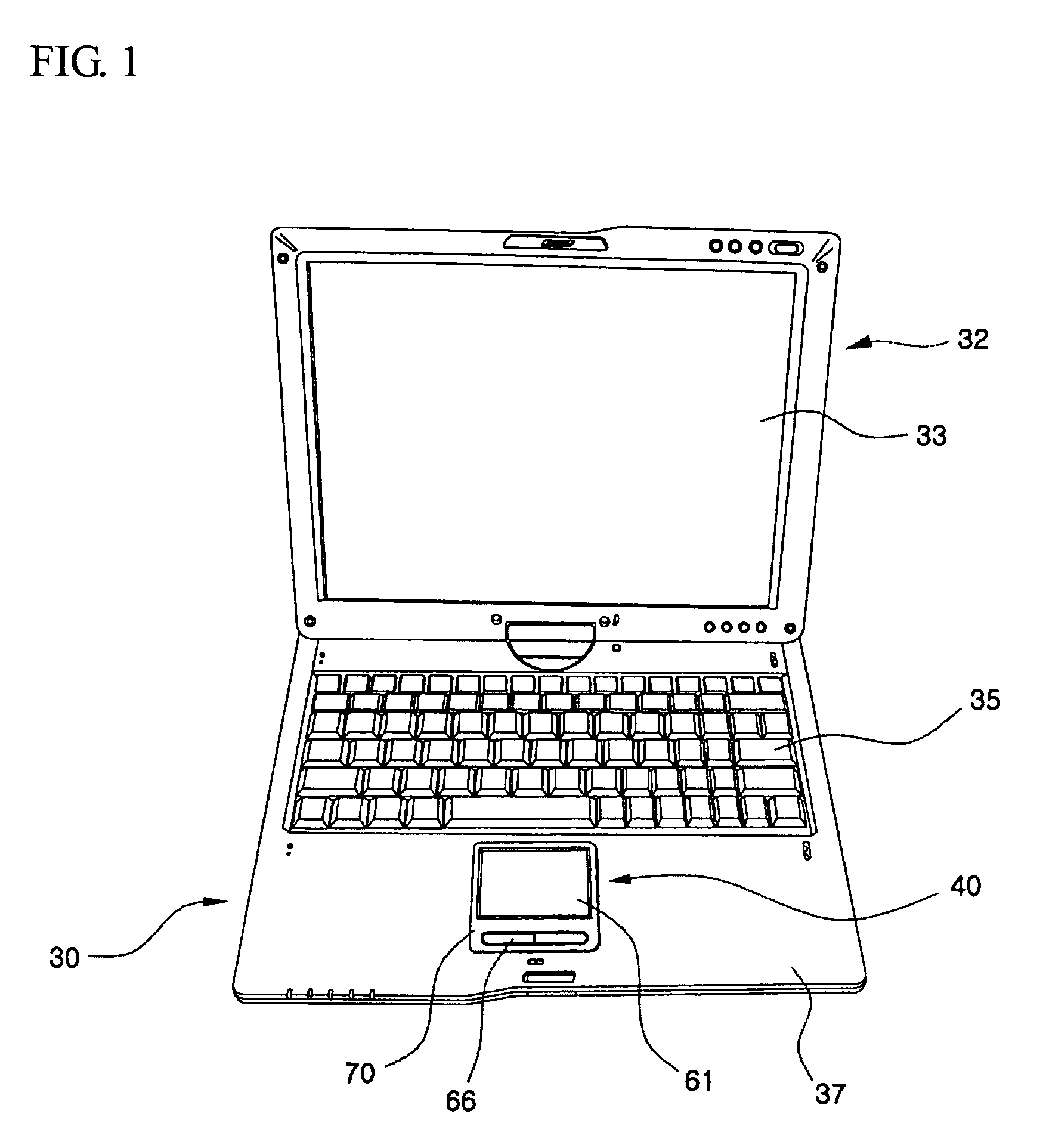
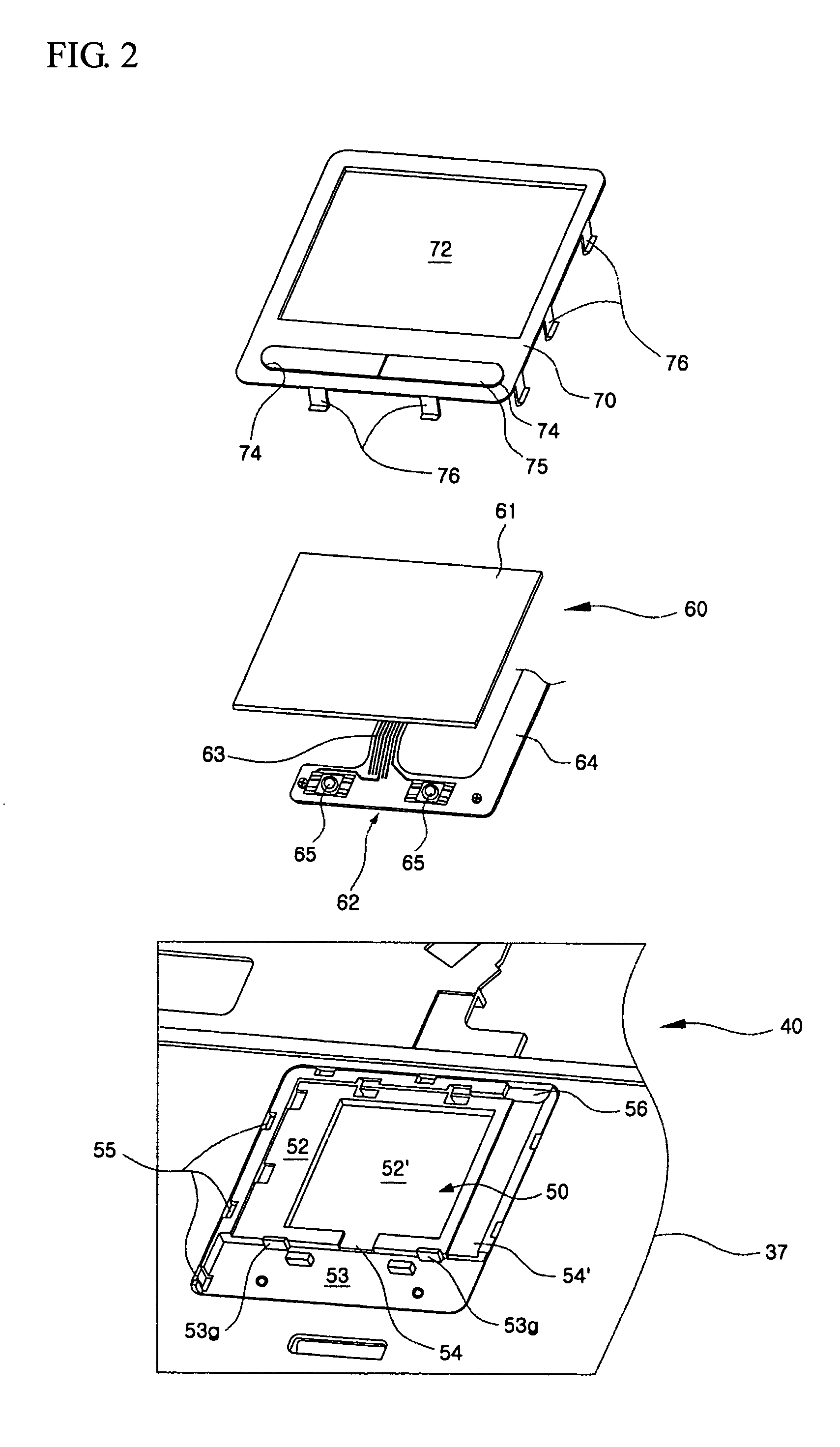
[0035]FIG. 1 is a perspective view showing the configuration of a portable computer to which the touch pad device according to an embodiment of the present invention is applied; FIG. 2 is an exploded perspective view showing the configuration of the embodiment of the present invention; and FIG. 3 is a partial bottom view showing the configuration of a key deck in which a touch pad housing according to the embodiment of the present invention is provided.

[0036]Referring to theses figures, the portable computer is configured in such a manner that a display unit 32 is hinged to and pivoted on a main body 30. The display unit 32 is connected to a rear end of the main body 30 such that the former can be folded onto a top surface of the latter or unfolded at a predetermined angle with respect to the latter....


PUM


Abstract

A touch pad device, for use in a portable computer, includes a touch pad housing that is recessed into and integrally formed on a top surface of a key deck. A pad assembly is securely seated into the touch pad housing and includes a touch pad. A pad cover is fastened to the touch pad housing, with the pad assembly installed therebetween, by hooks. Since the touch pad housing is integrally formed on the key deck, the number of component parts of the touch pad device is minimized and the man-hours for assembly is reduced. Further, since the pad cover can be installed and separated from above the key deck, maintenance of the pad assembly is simplified.

Description

[0001]The present application claims, under 35 U.S.C. § 119, the priority benefit of Korean Patent Application No. P03-055515 filed Aug. 11, 2003 in Republic of Korea, the entire contents of which are herein fully incorporated by reference.BACKGROUND OF THE INVENTION[0002]1. Field of the Invention[0003]The present invention relates to a portable computer, and more particularly, to a touch pad device that is used in a portable computer as an input device.[0004]2. Description of the Related Art[0005]Portable computers such as notebook computers generally employ a touch pad device or pointing stick as a pointing device that can be used instead of a mouse while they are carried. FIG. 5 shows a portable computer equipped with a related art touch pad device.[0006]As shown in FIG. 5, the portable computer is mainly composed of a main body 1 and a display unit 3. The display unit 3 can be folded onto a top surface of the main body 1 or unfolded at a predetermined angle as shown in this figu...

Claims


Application Information

Patent Timeline
Patent Type & Authority Patents(United States)
IPC IPC(8): G06F3/041G06F1/16G06F3/0354
CPCG06F1/1616G06F1/169G06F3/03547G06F1/16
Inventor SUN, YOU-MYOUNG
Owner LG ELECTRONICS INC
Learn More