Digital camera module test system

a digital camera and test system technology, applied in closed circuit television systems, color television details, television systems, etc., can solve problems such as complicated further, achieve the effect of determining the quality and capability of mut, facilitating the fast testing time of mut, and low serial overhead of parallel processing

Inactive Publication Date: 2009-02-03
RPX CORP
View PDF44 Cites 24 Cited by
  • Summary
  • Abstract
  • Description
  • Claims
  • Application Information

AI Technical Summary

Benefits of technology

[0012]It is an objective of the present invention to provide a test system to quickly and efficiently test a digital camera module.
[0019]The tester contains four separate parallel processors operating in parallel. Each processor is associated with its own memory performs calculations on a portion of an image captured from the MUT. A frame grabber associated the computer system of the tester synchronizes the light source of the test station with the clock of the MUT, captures a picture image from the MUT and stores that image into the memory associated with the corresponding parallel processor. Each of the parallel processors operate in parallel on different portions of the image collected from the MUT using computational routines such as fast Fourier transforms to analyze the image data. The use of the parallel processors operating in parallel reduces the time to make calculations on a image by approximately the number of parallel processors used. The data presently involves approximately three hundred thousand (300,000) pixels and is evolving to greater than mega-pixels (>1,000,000) in future miniature digital camera modules. Although, the test system of the present invention contains four parallel processors to compute the results of image tests on a digital camera module, the number parallel processors is not limited to four and can be less than or greater than four depending upon the requirements of the test system and the MUT.
[0020]The frame grabber synchronizes the light source and optical system contained within test station, captures a picture image from the digital camera MUT and stores a portion of the image into each memory associated with each parallel processor. Each of the parallel processors are used to operate on different portions of the picture image and each processor perform the calculations in parallel that are necessary to determine the picture taking capability of the MUT, reducing the pixel data to image parameters that are easily transmitted to the host processor coupled to the test system within the test time of a MUT.
[0022]For a MUT with a manual adjustable focus, an electrical contact is made to the MUT by the test station and the MUT is aligned under an optical reference line, The tester then controls the focus of the MUT leaving the final adjustment in place throughout the remainder of the testing of the MUT. When testing of the modules contained within a test tray is complete and the tray exits the test station, and the lens adjustment cap of each manually adjustable module is permanently fixed by using glue, a laser or any equivalent process that will permanently fix in place the focus of the manually adjustable lens cap on the MUT. For a MUT with automatic focus, the tester electrically controls the focus of the MUT and using the optical target system of the test station, insures that the focus range of the automatic focus meets the specifications of the digital camera having automatic focus capability.

Problems solved by technology

This is further complicated by the many different module configurations that are emerging as a result of the many different application requirements, including fixed focus, manual focus and automatic focus as well as physical size.

Method used


Image

  • Digital camera module test system
  • Digital camera module test system
  • Digital camera module test system

Examples


Embodiment Construction

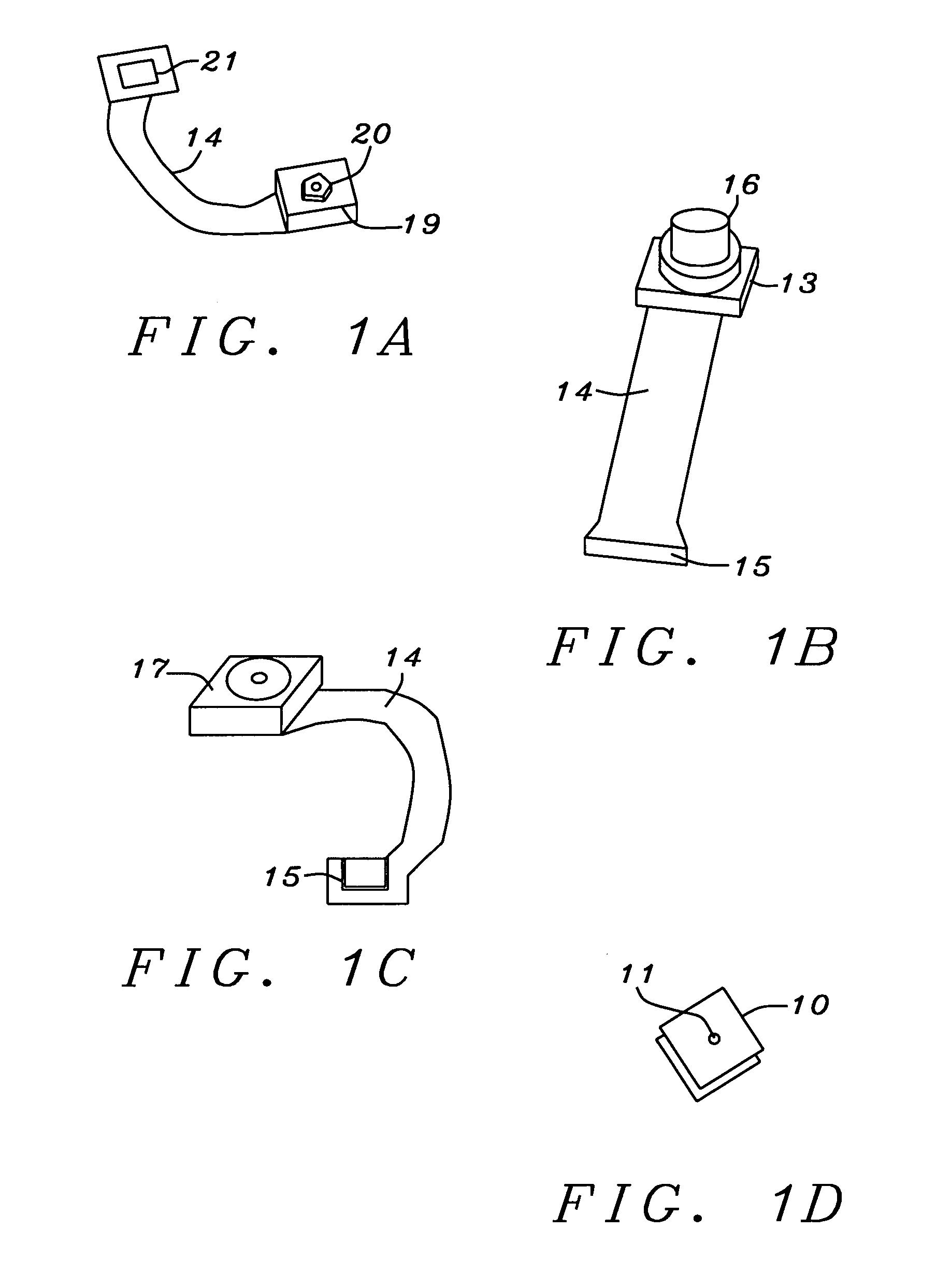
[0040]FIG. 1 shows examples of digital camera modules that are tested using the test system of the present invention. FIG. 1A is a digital camera module 19 with lens cap 20 having a hexagonal shape that allows manual focus adjustment. Other lens cap shapes can be used to allow manual focus adjustment, i.e. round, square, and octagonal. A flexible printed circuit 14 connects the module 19 to an electrical connector 21. The hexagonal shape of the lens cap, for example, allows a positive contact to a focus adjustment unit. FIG. 1B is a digital camera module 13 with a lens 16 having an automatic focus and a flexible printed circuit 14 to connect the digital camera module 13 to the connector 15. FIG. 1C is a fixed focus digital camera module 17 with a lead frame 14 connecting the module 17 to a connector 15. FIG. 1D is a leadless fixed focus module 10 in which the electrical contacts are located on the underneath side (not shown), and the lens opening 11 is centered in the middle of the ...


PUM


Abstract

A test system for digital camera modules used in consumer electronics, e.g. cellular phones and PDA's is shown. The test system comprises of a tester and a module handler that is aimed at reducing test time by an order of magnitude. The Test system has an image-processing unit that uses N-parallel processor to reduce the computation time on a test image by approximately the number of parallel processors. The handler is controlled by the tester to select, focus and test small digital camera modules. There are two test stations in the handler, where a first test station performs tests on a first camera module while a second test station is loaded with a second camera module, thus burying the loading time within the test time.

Description

RELATED PATENT APPLICATION[0001]This application is related to U.S. patent application, Ser. No. 10 / 929,651, filed on Aug. 30, 2004, and assigned to the same assignee as the present invention.[0002]This application is related to U.S. patent application, Ser. No. 10 / 930,353, filed on Aug. 31, 2004, and assigned to the same assignee as the present invention.[0003]This application is related to U.S. patent application, Ser. No. 10 / 929,652, filed on Aug. 30, 2004, and assigned to the same assignee as the present invention.[0004]This application is related to U.S. patent application, Ser. No. 10 / 929,300, filed on Aug. 30, 2004, and assigned to the same assignee as the present invention.[0005]This application is related to U.S. patent application, Ser. No. 10 / 929,653, filed on Aug. 30, 2004, and assigned to the same assignee as the present invention.BACKGROUND OF THE INVENTION[0006]1. Field of Invention[0007]The present invention relates to semiconductor test systems and in particular tes...

Claims


Application Information

Patent Timeline
Patent Type & Authority Patents(United States)
IPC IPC(8): H04N7/18H04N17/00G01M11/02
CPCH04N17/002
Inventor KNOEDGEN, HORSTHUETTMANN, DIRK
Owner RPX CORP
Why Eureka
Try Eureka