Arm chamfer for comb type actuator in rotating disk storage device and carriage assembly

a technology of rotating disk storage device and actuator arm, which is applied in the direction of magnetic recording, data recording, instruments, etc., can solve the problems of undulation of magnetic disk, unsatisfactory machining accuracy and mounting accuracy, and undergoes flutter, so as to reduce flutter, suppress both flutter of actuator arm, and improve positioning accuracy in servo control

Active Publication Date: 2009-02-03
WESTERN DIGITAL TECH INC
View PDF5 Cites 1 Cited by
  • Summary
  • Abstract
  • Description
  • Claims
  • Application Information

AI Technical Summary

Benefits of technology

[0011]It is a feature of the present invention to provide a magnetic disk drive capable of diminishing flutter which an actuator arm undergoes from an air flow created on a rotating recording medium and also capable of preventing the actuator arm itself from becoming a cause of flutter relative to a recording medium, thereby permitting improvement of the positioning accuracy in servo control.
[0013]When the first and second actuator arms are provided for the recording medium, each of the actuator arms is formed with a slant or chamfered face extending from a windward side face thereof toward a leeward side face thereof. Therefore, it is possible to not only suppress flutter of each actuator arm itself but also prevent each actuator arm from becoming a cause of flutter against a magnetic disk. By setting the length of the region of the slant face at 10% or less of the width of the actuator arm it is possible to suppress flutter of the actuator arm itself and machining of the slant face is easy.
[0014]If the slant face is formed from a boundary between the windward side face and the outer surface toward the inner surface, it is possible to eliminate a windward side face against which an air flow strikes and therefore a smoother air flow can be formed on the windward side of each actuator arm. Forming the slant face while allowing a part of the windward side face to remain is preferable from the standpoint of easiness of machining, but setting the height of the windward side face at a value in the range of 20% to 80% of the thickness of the actuator arm is effective in suppressing flutter.
[0015]If the slant faces of the first and second actuator arms are formed in such a manner that a plane including the slant face formed in the first actuator arm and a plane including the slant face formed in the second actuator arm intersect each other on a central plane of the rotating disk type recording medium, it is possible to balance the pressure which an air flow having changed its course at the slant face of each actuator arm applies to the recording surface. This is advantageous to diminish flutter given to the magnetic disk by the actuator arm. A wiring fixing portion and wiring supported thereby are apt to cause flutter of each actuator arm. It is preferable to dispose them on the leeward side and form the slant face on the windward side. This is advantageous to suppress flutter of each actuator arm.
[0017]In the case where two or more rotating disk type recording media are stacked, the second actuator arm is adopted as an actuator arm structure disposed between adjacent such recording media. For the outermost recording surface, the third actuator arm is disposed in symmetric relation to the first actuator arm with respect to a central plane in the height direction of the stack of magnetic disks. According to such a construction it is possible to suppress both flutter of the actuator arms and that of the magnetic disks even if the number of magnetic disks increases.
[0018]According to the present invention it is possible to provide a magnetic disk drive capable of diminishing flutter which each actuator arm undergoes from an air flow created by a rotating recording medium and capable of preventing each actuator arm from becoming a cause of flutter of the recording medium, thereby improving the positioning accuracy in servo control. Further, it is possible to provide a carriage assembly suitable for such a magnetic disk drive.

Problems solved by technology

The magnetic disk undergoes undulation which is attributable of unsatisfactory machining accuracy and mounting accuracy and also undergoes flutter under the influence of an air flow.
Therefore, even if side portions of the actuator arms are tapered to diminish oscillation or flutter of the actuator arms themselves, it is impossible to ensure a high-degree of head positioning accuracy when flutter occurs in the magnetic disks due to air flow changes at the tapered portions.

Method used


Image

  • Arm chamfer for comb type actuator in rotating disk storage device and carriage assembly
  • Arm chamfer for comb type actuator in rotating disk storage device and carriage assembly
  • Arm chamfer for comb type actuator in rotating disk storage device and carriage assembly

Examples


Embodiment Construction

[0024]Construction of Magnetic Disk Drive

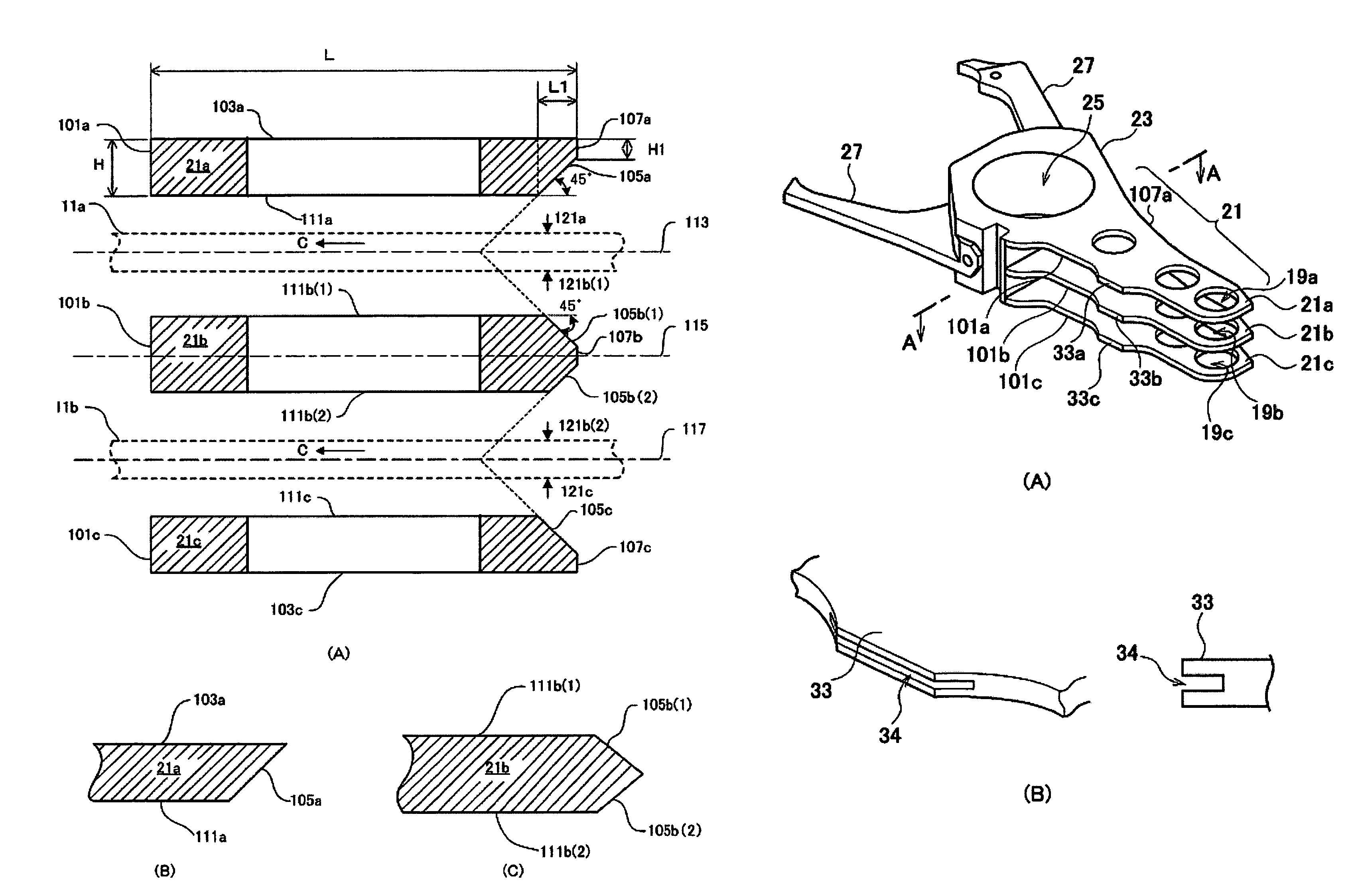
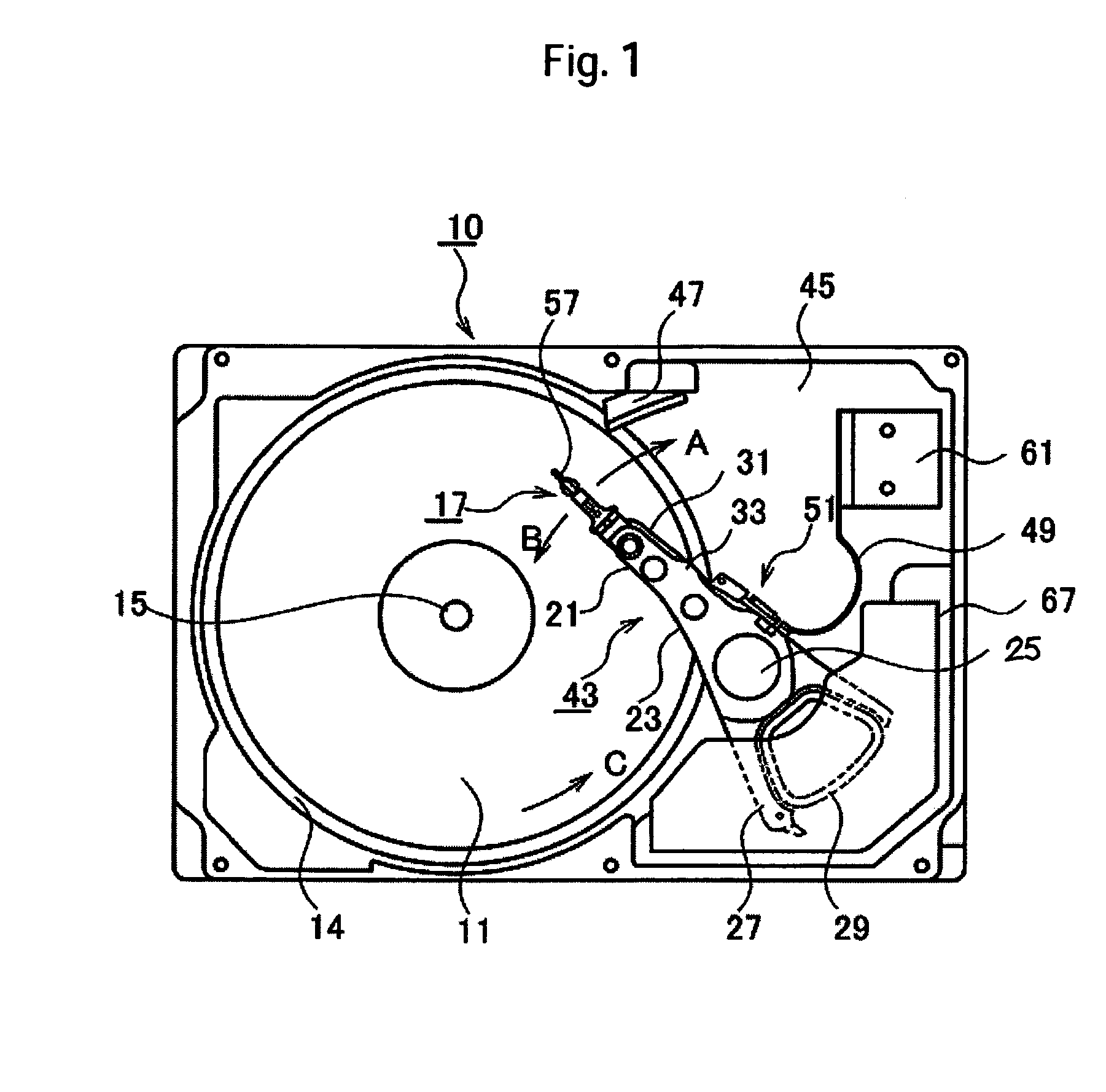
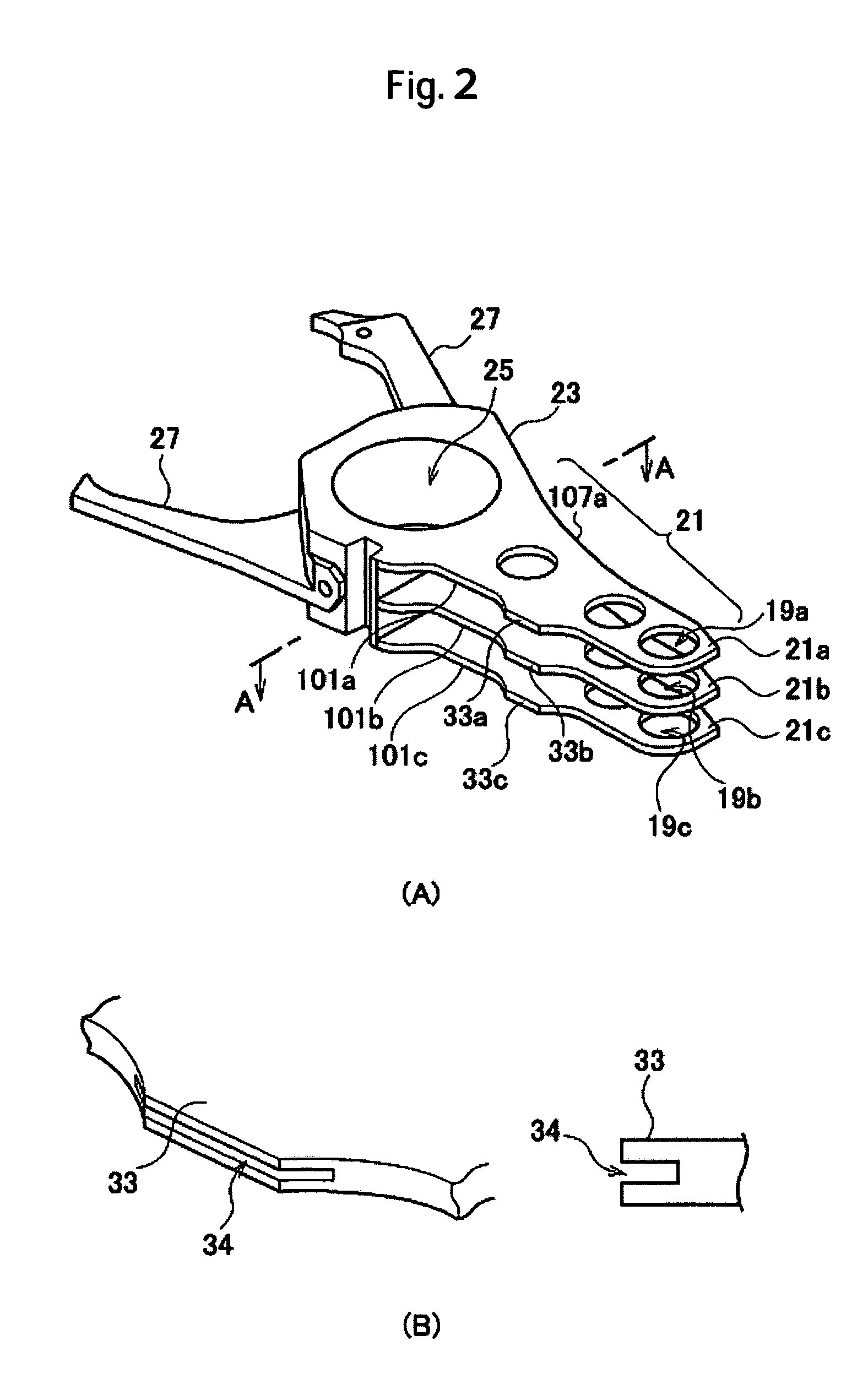
[0025]FIG. 1 is a schematic plan view of a magnetic disk drive according to an embodiment of the present invention. FIG. 2(A) is a perspective view showing a principal portion of a carriage assembly, and FIG. 2(B) is a detailed view of a slit. The magnetic disk drive 10 includes various constituent elements accommodated within a base 45. A magnetic disk stack 11 as recording media is composed of two magnetic disks 11a and 11b (neither shown) each having recording surfaces as both surfaces thereof. The magnetic disks are spaced at a predetermined distance from each other and fixed to a spindle hub. The magnetic disks 11a and 11b are driven by a spindle motor disposed at the bottom of the magnetic disk stack 11 and rotate together in the direction of arrow C around a spindle shaft 15.

[0026]In the two magnetic disks, an upper and lower magnetic disks are hereinafter denoted by 11a and 11b, respectively, as required. On each recording surface a p...


PUM

PropertyMeasurementUnit
angleaaaaaaaaaa
angleaaaaaaaaaa
lengthaaaaaaaaaa

Abstract

A carriage assembly capable of suppressing flutter of actuator arms and magnetic disk is to be provided. In one embodiment, the carriage assembly comprises a first actuator arm having a windward side face, a leeward side face, an outer surface and an inner surface, and a second actuator arm having a windward side face, a leeward side face, a first inner surface opposed to the inner surface of the first actuator arm and a second inner surface positioned on the side opposite to the first inner surface. The first actuator arm is formed with a slant face extending from the windward side face toward the inner surface and the second actuator arm is formed with a slant face extending from the windward side face toward the first inner surface and a slant face extending from the windward side face toward the second inner surface.

Description

CROSS-REFERENCES TO RELATED APPLICATIONS[0001]This application claim priority from Japanese Patent Application No. JP2004-345959, filed Nov. 30, 2004, the entire disclosure of which is incorporated herein by reference.BACKGROUND OF THE INVENTION[0002]The present invention relates to a technique for suppressing oscillation of an actuator arm to improve a position controlling performance for a magnetic head in a rotating disk storage device such as a magnetic disk drive or a magneto-optical disk drive. More specifically, it relates to a technique for not only suppressing oscillation of an actuator arm but also suppressing flutter of a magnetic head to improve a position controlling performance for the magnetic head.[0003]In a magnetic disk drive as an example of a rotating disk storage device, a head gimbal assembly (hereinafter referred to as “HGA”) is attached to an actuator arm of a carriage, the carriage being driven by a voice coil motor (hereinafter referred to as “VCM”) for piv...

Claims


Application Information

Patent Timeline
Patent Type & Authority Patents(United States)
IPC IPC(8): G11B5/55
CPCG11B5/5526
Inventor TSUJINO, HITOSHITSUCHIDA, HIROYASUTANIZAWA, HIROKAZUSUMIYA, TAKEJI
Owner WESTERN DIGITAL TECH INC
Why Eureka
Try Eureka