Applicator including a stem connected to a handle member via a hinge

a technology of hinges and hinges, applied in the field of applications comprising handle members, can solve problems such as difficulties

Inactive Publication Date: 2009-02-10
LOREAL SA
View PDF57 Cites 17 Cited by
  • Summary
  • Abstract
  • Description
  • Claims
  • Application Information

AI Technical Summary

Benefits of technology

[0009]A particular object of the invention is to propose a novel applicator, in particular for the lips, the eyelids, t

Problems solved by technology

Given the shape of the applicator element, difficulties can arise when the applicato

Method used


Image

  • Applicator including a stem connected to a handle member via a hinge
  • Applicator including a stem connected to a handle member via a hinge
  • Applicator including a stem connected to a handle member via a hinge

Examples


Embodiment Construction

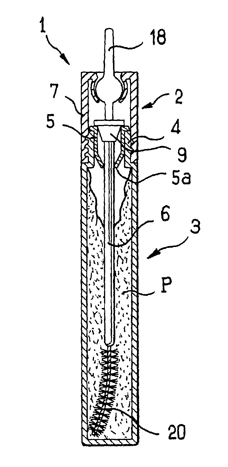
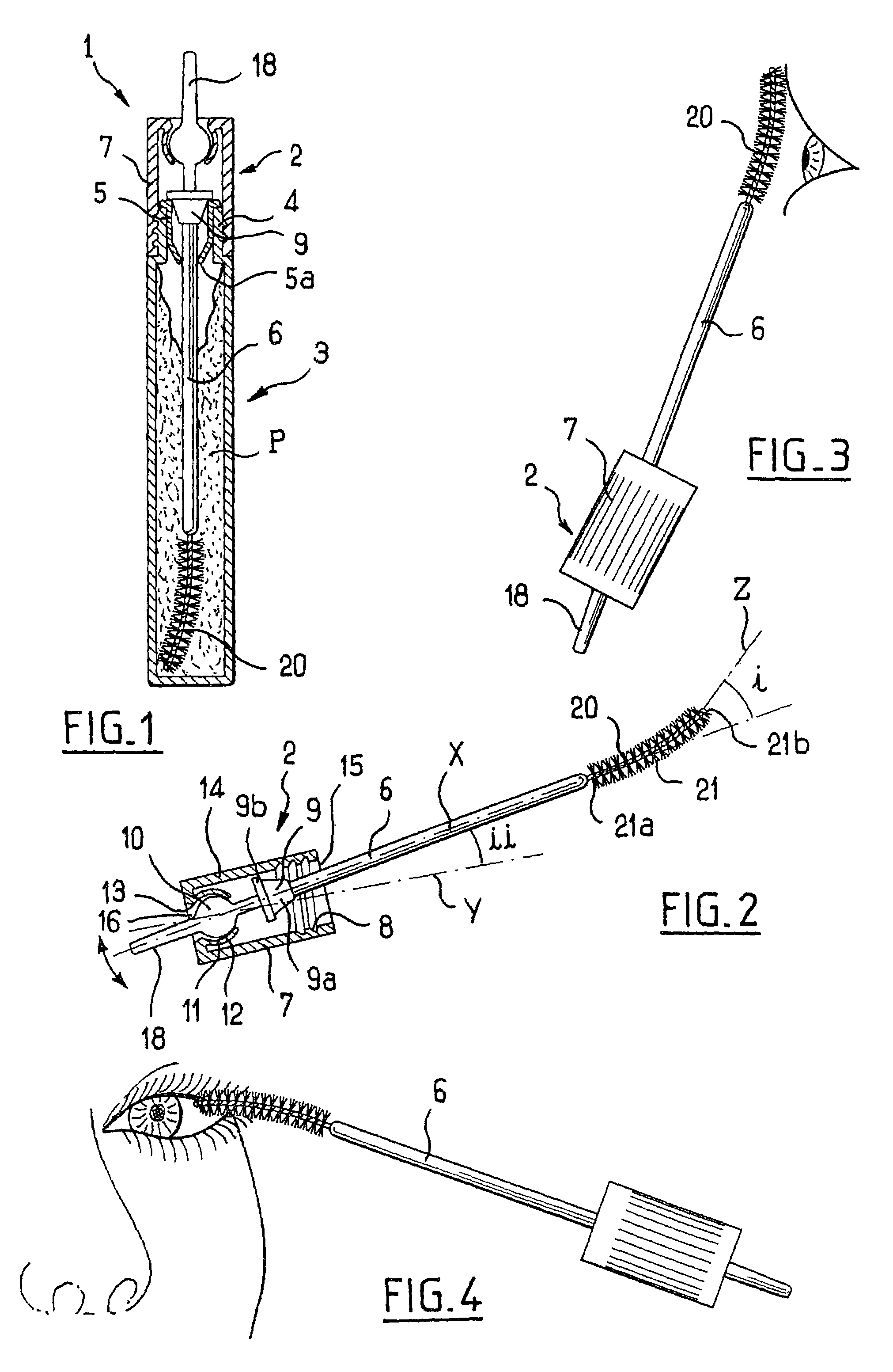
[0091]FIG. 1 shows a device 1 for applying makeup P to the eyelashes or the eyebrows, e.g. mascara, the device comprising an applicator 2 shown on its own in FIGS. 2 and 3 and a receptacle 3 containing the makeup P and on which the applicator 2 can be fixed in substantially leaktight manner when not in use. In conventional manner, the receptacle 3 may have a threaded neck 4, as shown in FIG. 1, with a wiper 5 being fixed inside the threaded neck, the wiper being made out of elastomer, for example, and possibly comprising a flexible lip that is generally conical in shape.

[0092]In the example shown, the applicator 2 comprises a rectilinear stem 6 of axis X together with a handle member 7 of axis Y that also serves as a closure cap for the receptacle 3, being provided for this purpose with an inside thread 8 configured to screw onto the neck 4.

[0093]The stem 6 has a sealing member 9 configured to co-operate with the opening of the receptacle 3 when the applicator 2 is in place thereon,...


PUM


Abstract

The present invention provides an applicator comprising:
    • a handle member;
    • a stem connected via a hinge to the handle member; and
    • an applicator element disposed at a first end of the stem and configured to apply makeup on keratinous fibers;
    • the stem including a maneuverable portion enabling the direction in which it points relative to the handle member to be modified, the maneuverable portion extending at least in part between the hinge and a second end of the stem opposite from its first end.

Description

CROSS REFERENCE TO RELATED APPLICATIONS[0001]The present application claims the benefit of French patent application number 02-07060, filed Jun. 7, 2002; French patent application number 02-07061, filed Jun.7, 2002; U.S. provisional patent application No. 60 / 388,308, filed Jun. 14, 2002; and U.S. provisional patent application No. 60 / 388,309, filed Jun. 14, 2002, the disclosures of which are hereby incorporated by reference.BACKGROUND OF THE INVENTION[0002](i) Field of the Invention[0003]The present invention relates to applicators comprising a handle member, a stem connected via a hinge to the handle member, and an applicator element disposed at one end of the stem.[0004](ii) Description of Related Art[0005]Such applicators, which are suitable for applying a cosmetic, are described in U.S. Pat. No. 6,026,823.[0006]Other applicators are described in: U.S. Pat. No. 5,328,282, U.S. Pat. No. 2,173,959, U.S. Pat. No. 4,396,029, U.S. Pat. No. 5,435,328, FR 2 701 196, U.S. Pat. No. 4,165,...

Claims


Application Information

Patent Timeline
IPC IPC(8): A45D40/26
CPCA45D40/267
Inventor GUERET, JEAN-LOUIS
Owner LOREAL SA
Why Eureka
Try Eureka