Liquid cooled rotor assembly

a rotor assembly and liquid cooling technology, applied in the direction of magnetic circuit rotating parts, dynamo-electric machines, magnetic circuit shape/form/construction, etc., can solve problems such as difficult motor cooling, and achieve the effect of promoting the directional change of coolan

Active Publication Date: 2009-02-10
TESLA INC
View PDF9 Cites 69 Cited by
  • Summary
  • Abstract
  • Description
  • Claims
  • Application Information

AI Technical Summary

Benefits of technology

[0009]In at least one embodiment of the invention, the inner surface of the closed end of the rotor shaft is shaped, thereby promoting the directional change of the coolant from a first direction through the feed tube to a second direction through the coolant flow region between the outer surface of the feed tube and the inner surface of the rotor shaft.

Problems solved by technology

Electric motors can generate considerable heat, thereby making motor cooling difficult, especially in the traction motor of a vehicle where size and weight constraints are coupled with the need for high output.

Method used


Image

  • Liquid cooled rotor assembly
  • Liquid cooled rotor assembly
  • Liquid cooled rotor assembly

Examples


Embodiment Construction

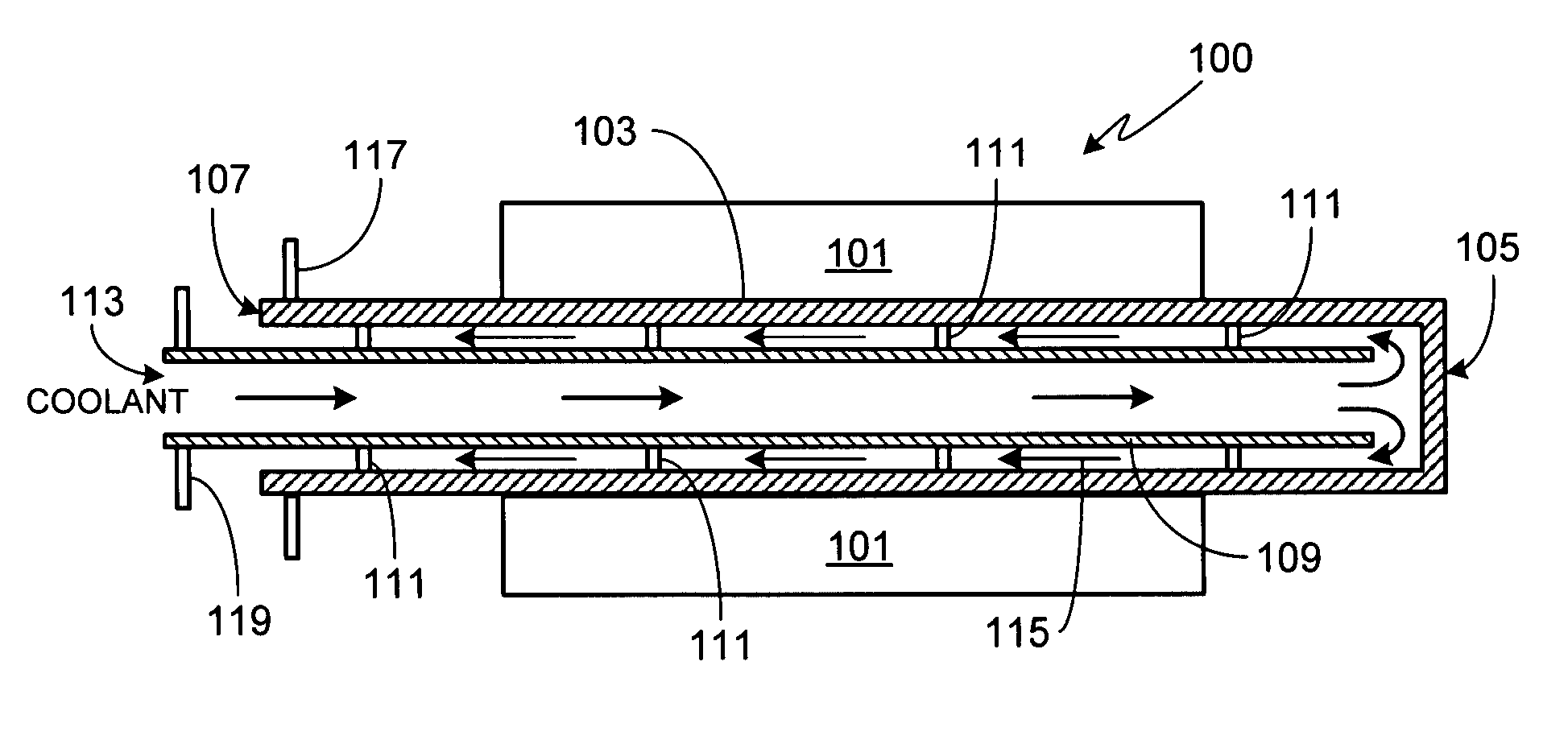
[0019]FIG. 1 schematically illustrates the primary components of the rotor assembly cooling system of the invention. Rotor assembly 100 includes a rotor 101 fixed to a rotor drive shaft 103. Drive shaft 103 is hollow and closed at end 105 and open at end 107. Although not a requirement of the invention, preferably shaft 103 is hollow over the majority of its length, including that portion of the shaft in contact with rotor 101, thereby insuring efficient cooling of the rotor assembly. A hollow coolant feed tube 109 is rigidly attached to shaft 103 with at least one, and preferably a plurality of support members 111.

[0020]During operation, coolant is pumped into end 113 of feed tube 109. The coolant flows through the length of feed tube 109 until it is redirected by the inside surface of closed end 105 of shaft 103. The coolant than flows back along direction 115 towards the inlet, passing within the coolant flow region between the outer surface of feed tube 109 and the inside surfac...


PUM


Abstract

A rotor assembly cooling system (100) and method of using same are provided. A portion of the rotor shaft (103) is hollow, the rotor shaft including an open end (107) and a closed end (105). A coolant feed tube (109) is rigidly attached to the rotor shaft (103) using one or more support members (111), thus causing the shaft and the feed tube to rotate at the same rate. Coolant is pumped through the feed tube until it exits the end of the feed tube and flows against the inside surface of the closed end of the rotor shaft causing the coolant to change direction and flow back through the coolant flow region, this region being defined as the space between the outer surface of the feed tube and the inner surface of the hollow rotor shaft.

Description

FIELD OF THE INVENTION[0001]The present invention relates generally to electric vehicles and, more particularly, to a method and apparatus for efficiently cooling the rotor in the drive motor of an electric vehicle.BACKGROUND OF THE INVENTION[0002]Electric motors can generate considerable heat, thereby making motor cooling difficult, especially in the traction motor of a vehicle where size and weight constraints are coupled with the need for high output. Additionally, in order to avoid excessive wear due to differential thermal expansion, it is important to cool the internal motor components (e.g., rotor) as well as the outer motor components (e.g., casing, stator). Lastly, the means used to cool the motor must not be susceptible to large variations in the operating environment as such a motor can be expected to be subjected to a wide range of ambient temperatures, humidity levels and dust / dirt levels.[0003]A number of different approaches have been taken to meeting the cooling dema...

Claims


Application Information

Patent Timeline
Patent Type & Authority Patents(United States)
IPC IPC(8): H02K1/32H02K9/00H02K9/06
CPCH02K9/19H02K9/197
Inventor ZHOU, PENGKALAYJIAN, NICHOLAS ROBERTCUTLER, GRANT DUFRESNEAUGENBERGS, PETERIS KOCH
Owner TESLA INC
Why Eureka
Try Eureka