Optical displacement meter, optical displacement measuring method, optical displacement measuring program, computer-readable recording medium, and device that records the program

a technology of optical displacement measurement and optical displacement, applied in the direction of measuring devices, instruments, using optical means, etc., can solve the problems of measurement accuracy deterioration and difficulty in performing work, and achieve the effect of accurate position adjustmen

Active Publication Date: 2009-02-10
KEYENCE
View PDF7 Cites 27 Cited by
  • Summary
  • Abstract
  • Description
  • Claims
  • Application Information

AI Technical Summary

Problems solved by technology

When the reception light signal is too small, or too large due to saturation or the like, the measurement accuracy deteriorates.
However, the accurate position has to be set with high precision, and it is difficult to perform the work.

Method used


Image

  • Optical displacement meter, optical displacement measuring method, optical displacement measuring program, computer-readable recording medium, and device that records the program
  • Optical displacement meter, optical displacement measuring method, optical displacement measuring program, computer-readable recording medium, and device that records the program
  • Optical displacement meter, optical displacement measuring method, optical displacement measuring program, computer-readable recording medium, and device that records the program

Examples


first embodiment

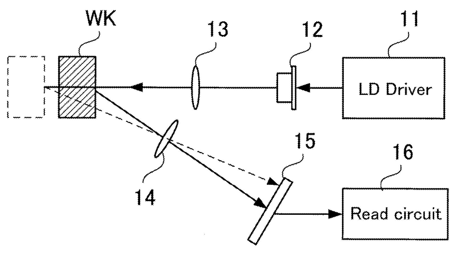
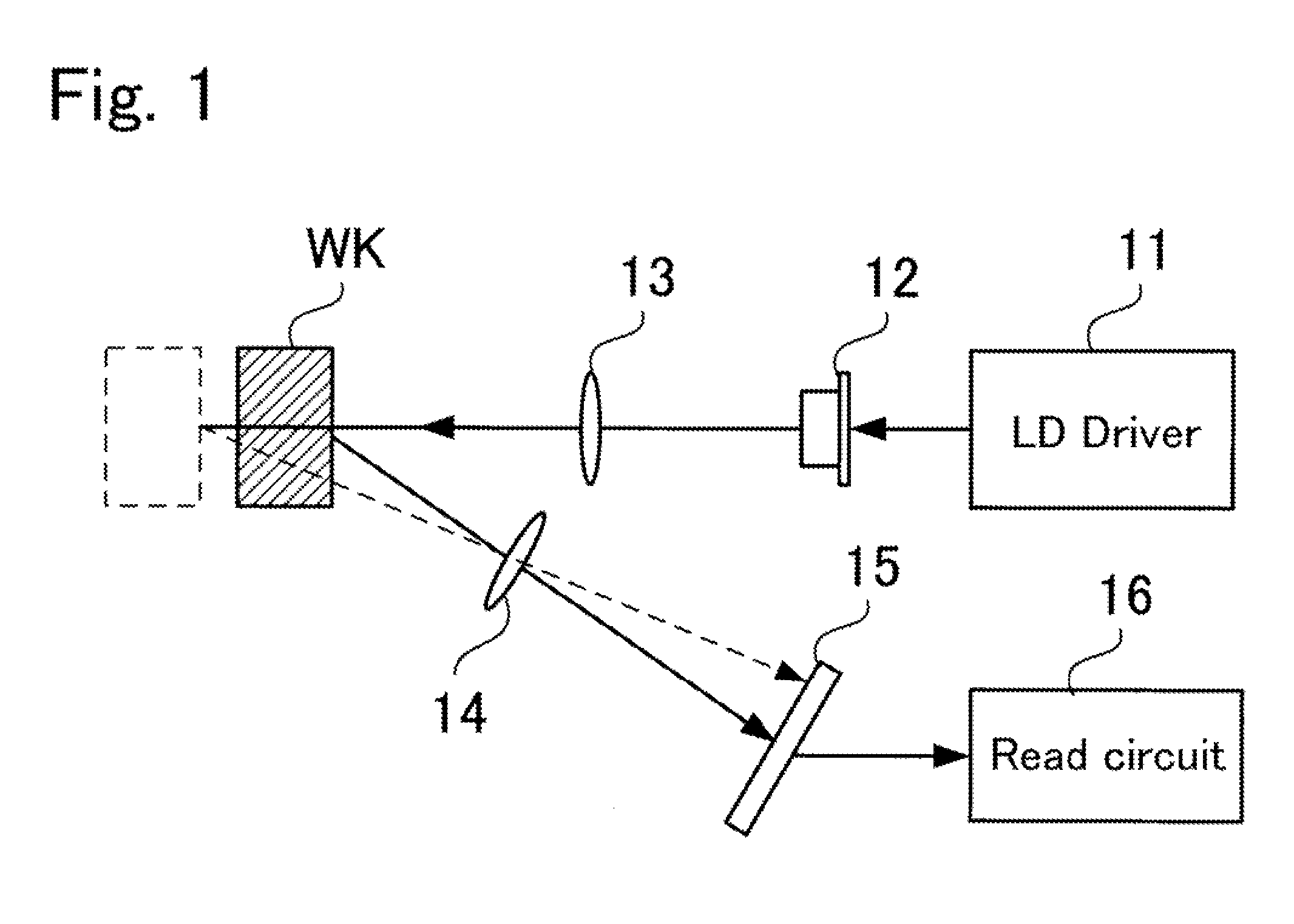
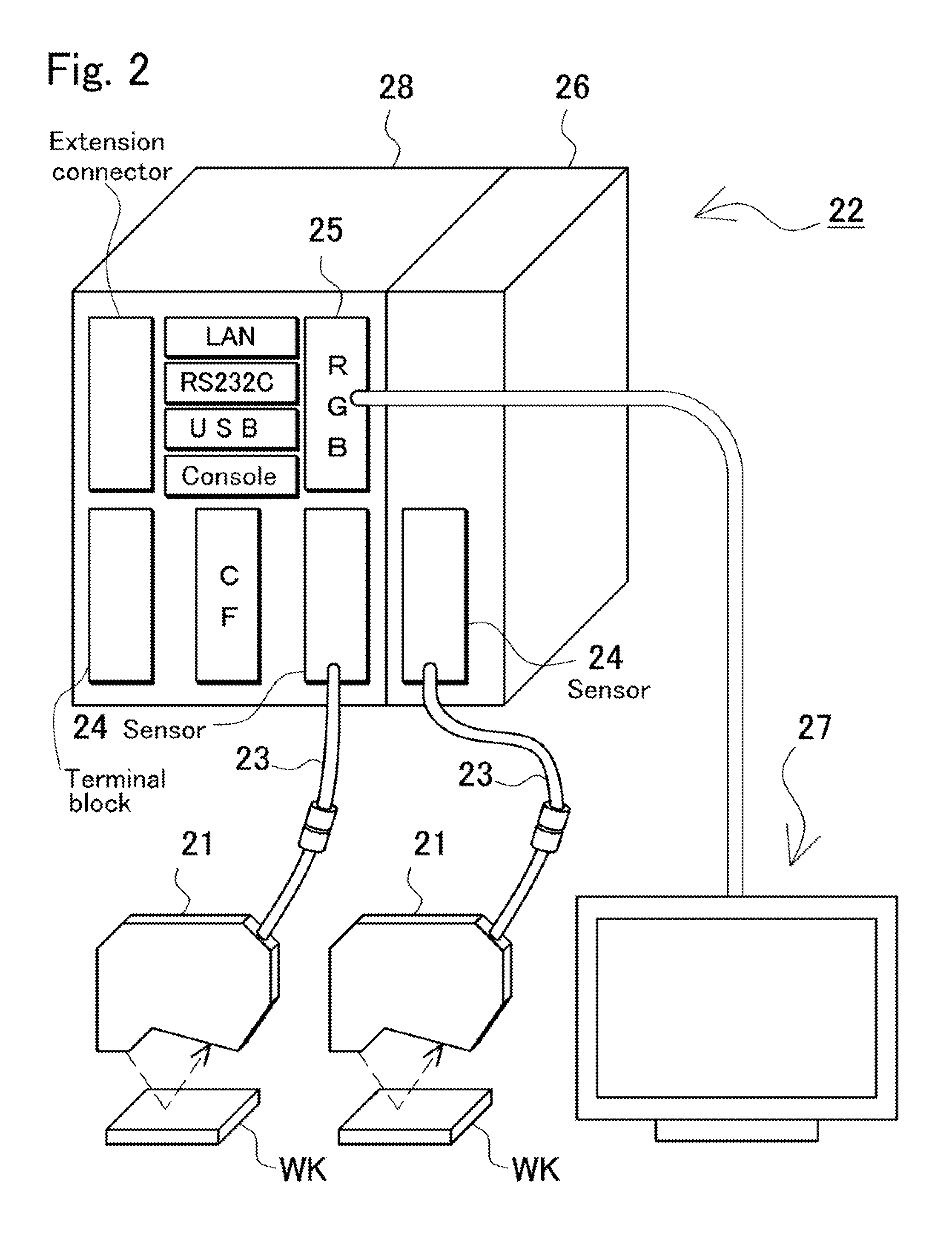
[0127]FIGS. 1 to 3 show an optical displacement meter 100 as a first embodiment of the present invention. FIG. 1 is a block diagram showing the configuration of the optical displacement meter 100 as a first embodiment of the invention. FIG. 2 is a perspective view showing the system configuration of the optical displacement meter 100. FIG. 3 is a block diagram showing the configuration of feedback control performed by a microprocessor 44. An example of the feedback control will be mainly described.

[0128]FIG. 1 shows the measurement principle of the optical displacement meter 100. The optical displacement meter 100 is also called a laser displacement meter and used for measuring a displacement of an object in a non-contact manner by using the principle of triangulation. A laser beam emitted from a laser diode 12 under control of an LD driver 11 passes through a projection lens 13 and falls on a work WK. A part of the laser beam reflected from the work WK passes through a light recept...

second embodiment

[0138]FIG. 4 is a block diagram of an optical displacement meter 200 as a second embodiment of the present invention. The optical displacement meter 200 shown in the diagram is also constructed by connecting a sensor head 1 and a controller 2. The sensor head 1 has a projector 3 for emitting band light (strip line) to the work WK and the two-dimensional light receiving device 15 for receiving reflection light of the band light, capturing a light reception image, and outputting the image as a light reception signal in positions in a first direction. The controller 2 includes: a light amount control unit 51 such as a driver for controlling the light amount of a light projecting element included in the projector 3; a light receiving device control unit 52 for controlling the light reception characteristic of the two-dimensional light receiving device 15; an image reader 56 for reading a light reception image captured by the light receiving device; a light reception data control unit 60...

third embodiment

[0218]The optical displacement meter in which one sensor head is connected to one controller has been described. Head connectors for connecting two or more sensor heads to a single controller may be also provided. FIG. 40 shows a third embodiment in which a controller has head connectors 4 capable of connecting two sensor heads. In the optical displacement meter, a process using the two sensor heads can be performed. To be specific, different parts in the same work are measured by the two sensor heads, the same work is measured at different timings, or different works can be measured. By combining results of the computations, a high-degree measurement is realized. FIG. 41A shows an example of arranging two sensor heads side by side to substantially enlarge a measurable area. Ideally, by disposing the sensor heads in the same posture with respect to the work WK8, profile shapes obtained from the sensor heads as shown in FIG. 41B can be combined as shown in FIG. 41C. In reality, howev...


PUM


Abstract

The present invention provides an optical displacement meter which performs a profile search for performing positional adjustment of a profile shape. The optical displacement meter includes: an amplifier for amplifying a reception light signal from a two-dimensional light receiving device; profile computing means capable of computing a profile shape of the object to be measured on the basis of an amplification signal obtained by the amplifier in a point in the first direction by the reflection light of the light emitted from the projector; a display unit capable of displaying the profile shape of the object to be measured computed by the profile computing means; registered-profile designating means for designating a registered profile as a reference of a profile search from profile shapes displayed on the display unit; and profile matching means for performing a profile search to find a match between an input profile shape and the registered profile designated by the registered profile designating means and, on the basis of a result of the profile search, rotating or moving the input profile shape.

Description

BACKGROUND OF THE INVENTION[0001]1. Field of the Invention[0002]The present invention relates to an optical displacement meter, an optical displacement measuring method, an optical displacement measurement program, a computer-readable recording medium, and a device that records the program, for irradiating an object to be measured with light, receiving the light from the object to be measured with a light receiving device to obtaining an electric signal according to the receiving light, measuring a distance from a light projector to the object to be measured, a displacement of the object to be measured, and the like corresponding to the electrical signal.[0003]2. Description of the Related Art[0004]To measure the dimension, a movement amount, and the like of an object to be measured (work), an optical displacement meter to which triangulation is applied is used. FIG. 93 is a block diagram showing the configuration of main components of a conventional optical displacement meter. In F...

Claims


Application Information

Patent Timeline
Patent Type & Authority Patents(United States)
IPC IPC(8): G01B11/14
CPCG01B11/026G01B11/24
Inventor NISHIO, YOSHIAKI
Owner KEYENCE
Why Eureka
Try Eureka