
Bicycle frame with device cavity

Active Publication Date: 2008-10-16
TREK BICYCLE CORPORATION
View PDF26 Cites 19 Cited by
  • Summary
  • Abstract
  • Description
  • Claims
  • Application Information

AI Technical Summary

Benefits of technology

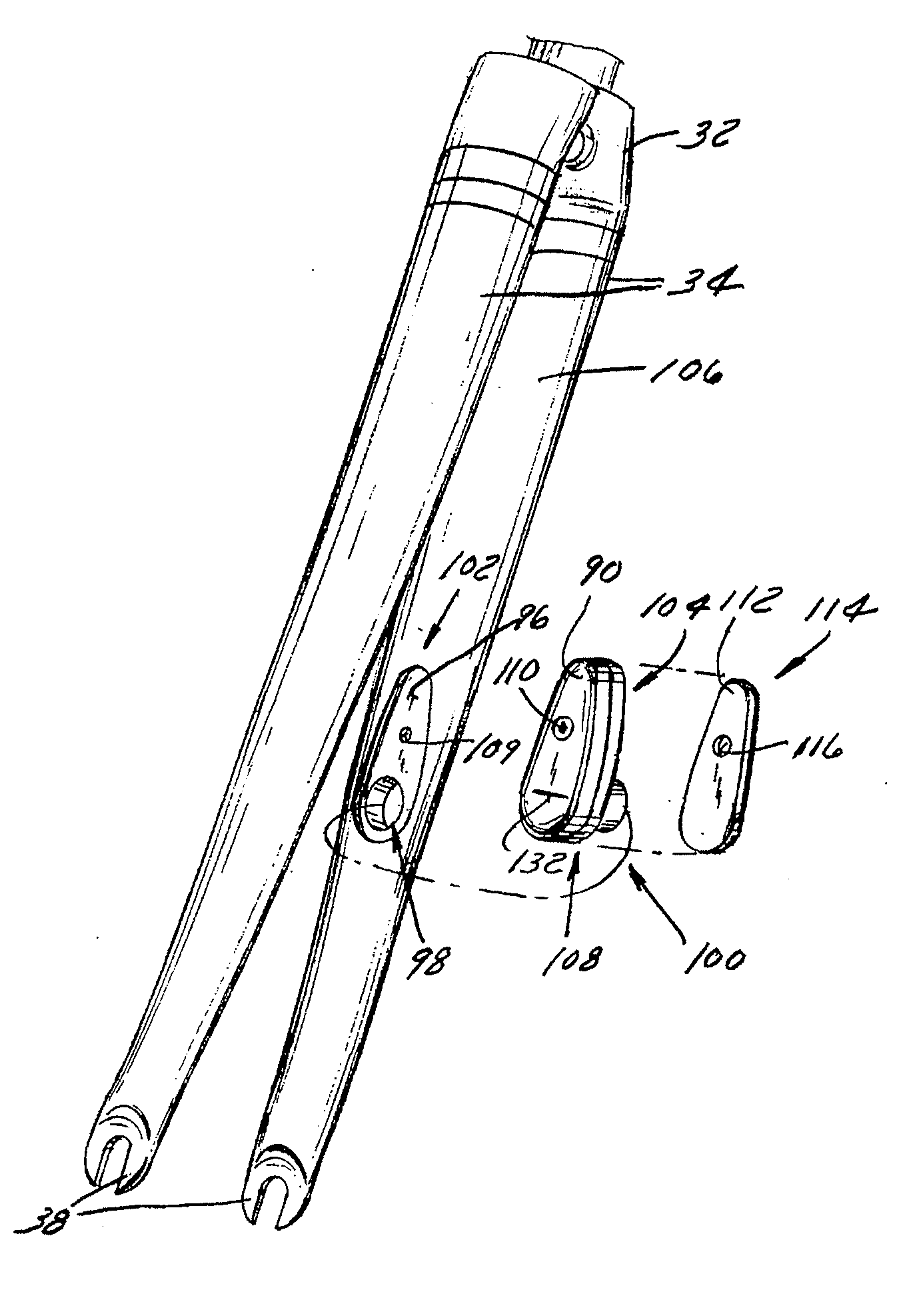
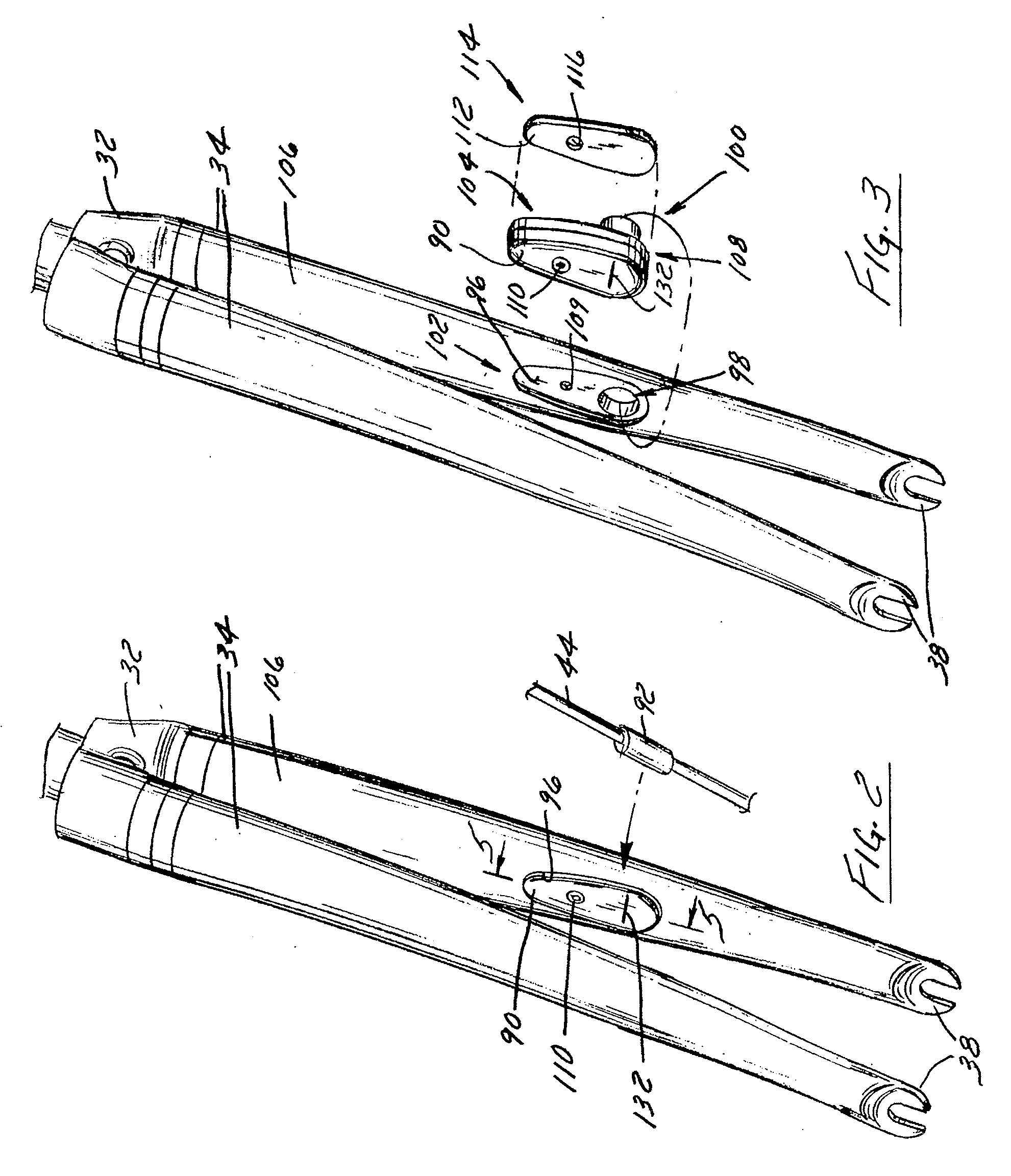
[0011]A bicycle frame according to another aspect of the invention has a first portion for engaging a front tire, a second portion for engaging a rear tire, and a third portion for supporting a rider. A recess is formed in one of the portions of the frame for receiving a first sensor component configured to wirelessly communicate with a second sensor component. Preferably, the recess is formed in a fork or tube and the first sensor component is a sensor configured to monitor passage of an operator attached to a wheel and communicate the monitored information to the second sensor component that is a remote receiver. Such a construction reduces the aesthetic and aerodynamic impact of a sensor system.
[0013]Another aspect of the invention discloses a method of constructing a bicycle. The method includes forming a frame to support a pair of wheels and forming a cavity in an exterior surface of a portion of the frame. The cavity is contoured to receive a sensor that is constructed to wirelessly communicate with a receiver positioned remotely from the sensor. Accordingly, such a method provides a bicycle configured to provide for the incorporation of one or more sensor systems within a profile of the bicycle frame. Such a configuration further reduces the potential for theft and / or damage of the components of the sensor system.

Problems solved by technology

Such a construction reduces the aesthetic and aerodynamic impact of a sensor system.

Method used


Image

  • Bicycle frame with device cavity
  • Bicycle frame with device cavity
  • Bicycle frame with device cavity

Examples


Embodiment Construction

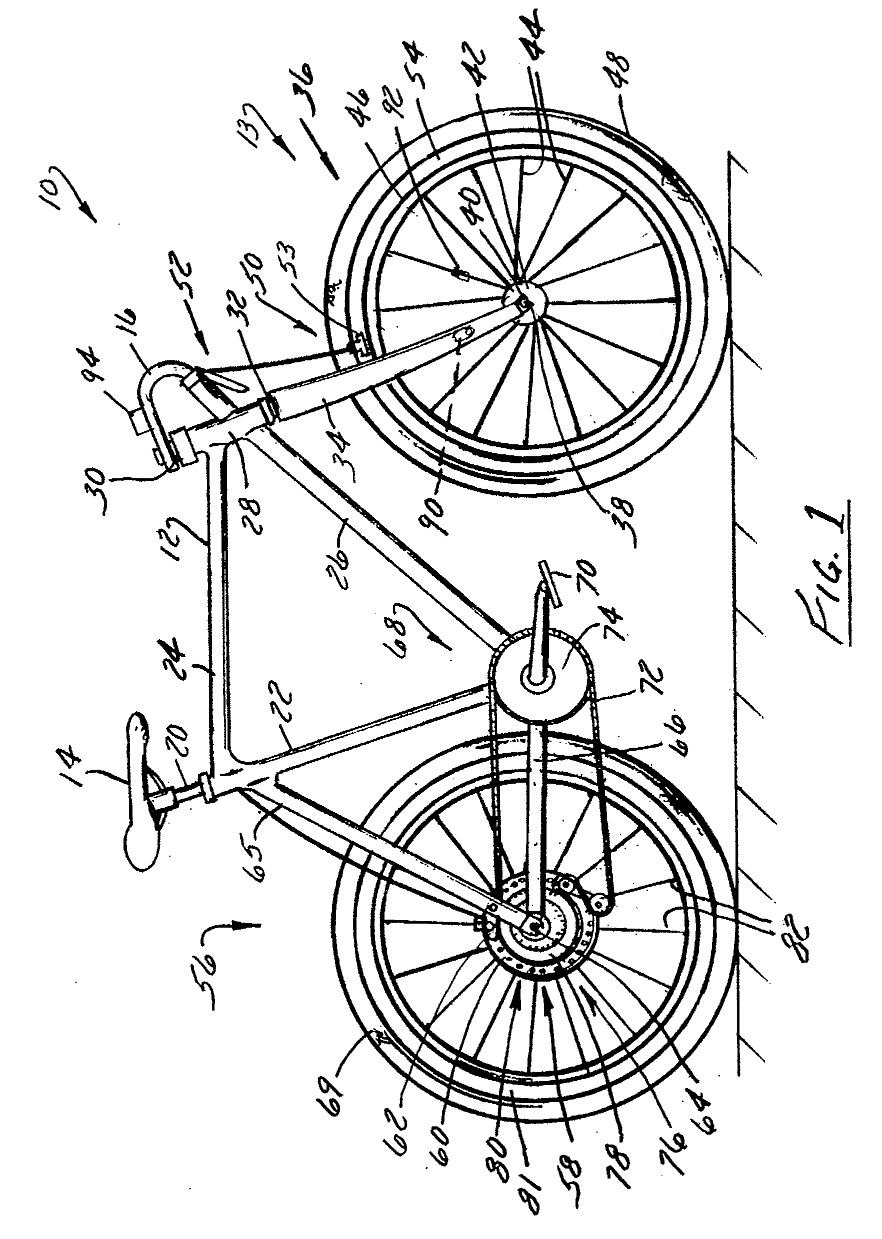
[0022]FIG. 1 shows a bicycle 10 having a frame 12 constructed to accommodate a sensor system 13 according to the present invention. Bicycle 10 includes a seat 14 and handlebars 16 that are attached to frame 12. A seat post 20 is connected to seat 14 and slidably engages a seat tube 22 of frame 12. A top tube 24 and a down tube 26 extend forwardly from seat tube 22 to a head tube 28 of frame 12. Handlebars 16 are connected to a stem 30 that passes through head tube 28 and engages a fork crown 32. A pair of forks 34 extend from generally opposite ends of fork crown 32 and are constructed to support a front wheel assembly 36 at an end thereof or fork tip 38. Fork tips 38 engage generally opposite sides of an axle 40 that is constructed to engage a hub 42 of front wheel assembly 36. A number of spokes 44 extend from hub 42 to a rim 46 of front wheel assembly 36. A tire 48 is engaged with rim 46 such that rotation of tire 48, relative to forks 34, rotates rim 46 and hub 42.

[0023]Bicycle ...


PUM


Abstract

A bicycle frame having a cavity constructed to receive a sensor device. The cavity has a shape and a contour that generally matches a shape and a contour of the sensor device. Such a configuration maintains the aerodynamic contour of the frame when the sensor device is positioned in the cavity. An optional plug occupies the cavity when the sensor device is not positioned therein. Preferably, the sensor device is constructed to wirelessly communicate bicycle operation information to a receiver that is remotely located relative to the sensor device. More preferably, the cavity is formed in a fork of the bicycle and the sensor device is configured to monitor operation of a front wheel and wirelessly communicate the operation information to the remote receiver.

Description

BACKGROUND OF THE INVENTION[0001]The present invention relates generally to bicycles and, more particularly, to bicycle frames and operation monitoring systems.[0002]During cycling, cyclists frequently desire to know information relative to their performance. Desired information can include trip specific information such as speed, distance traveled, duration, and cadence and / or comparative information such as information related to a comparison of past and current performance. Frequently, operational information is acquired by a sensor system that monitors bicycle performance and generates the requested information. That portion of the sensor system configured to monitor bicycle performance generally includes a detector that is positionally fixed relative to an operator attached to a mobile component of the bicycle, such as a wheel or a crank arm. The operator attached to the wheel repeatedly passes the detector thereby providing information relative to movement of the wheel and the...

Claims


Application Information

Patent Timeline
IPC IPC(8): B62K3/02
CPCB62J99/00B62J2099/002B62K3/04B62K21/02B62K2207/00B62J45/423B62J45/421B62J45/412
Inventor BLOMME, DAVID J.DACKO, DANLEWIS, BARRY
Owner TREK BICYCLE CORPORATION
Learn More