Spin-transfer switching magnetic elements using ferrimagnets and magnetic memories using the magnetic elements

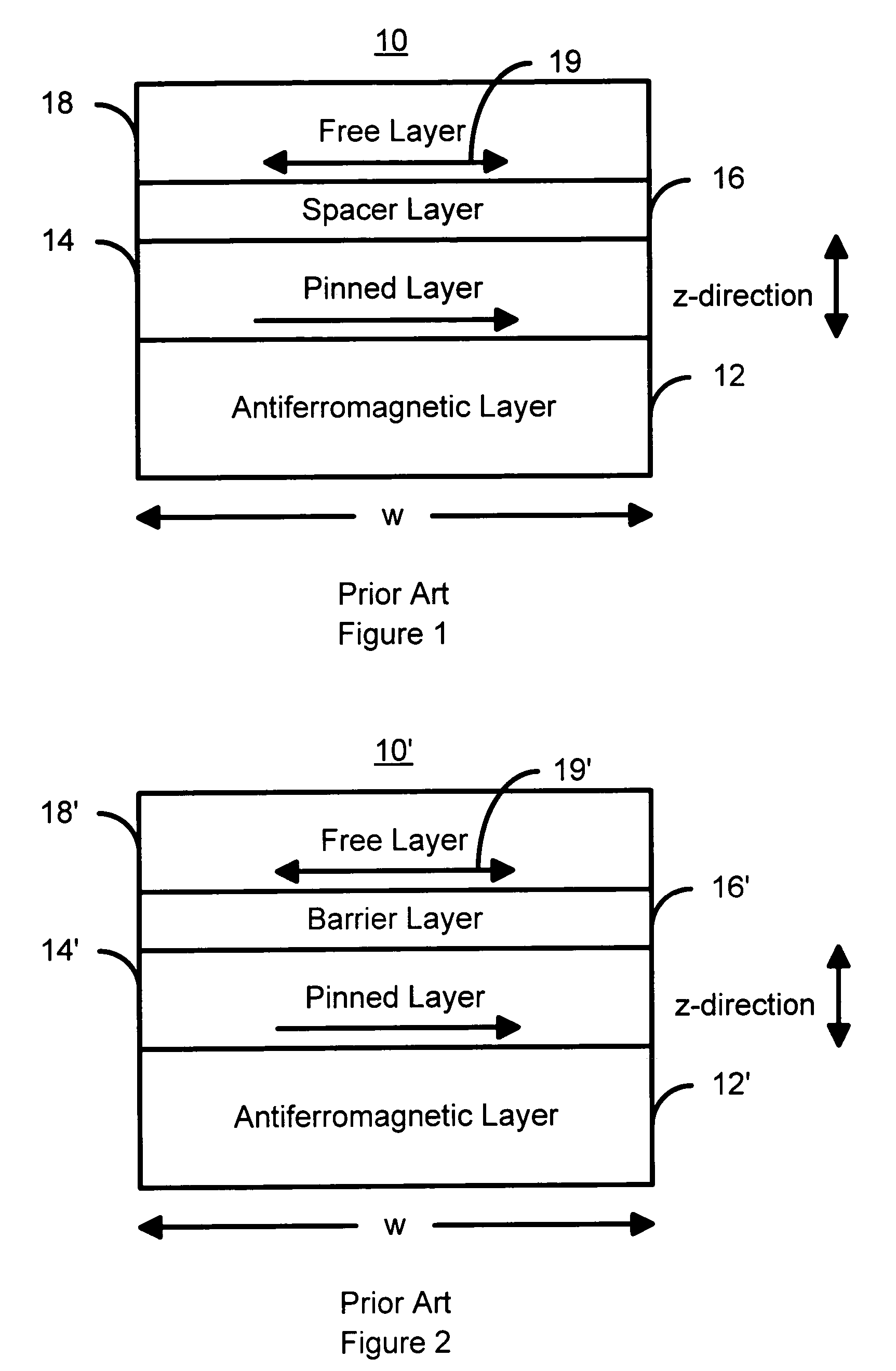
a technology of ferrimagnets and magnetic elements, applied in the field of magnetic memory systems, can solve the problems of increasing power consumption, adversely affecting the utility and reliability of such conventional magnetic elements, and conventional magnetic elements b>10/b>

Active Publication Date: 2009-02-10
SAMSUNG SEMICON
View PDF13 Cites 158 Cited by
  • Summary
  • Abstract
  • Description
  • Claims
  • Application Information

AI Technical Summary

Problems solved by technology

Use of a high critical current for switching the magnetization 19 / 19′ adversely affects the utility and reliability of such conventional magnetic elements 10 / 10′ in a magnetic memory.
The use of a high write current is associated with increased power consumption, which is undesirable.
In addition, the conventional magnetic element 10′, which has a higher resistance and thus a higher signal, may be less reliable because the conventional barrier layer 16′ may be subject to dielectric breakdown at higher write currents.
Thus, even though a higher signal read may be achieved, the conventional magnetic elements 10 / 10′ may be unsuitable for use in higher density conventional MRAMs using a high spin transfer switching current to write to the conventional magnetic elements 10 / 10′.
Moreover, although mechanisms for reducing the high current density have been proposed, such as in Noziere, these mechanisms have issues such as a potential loss in signal.

Method used


Image

  • Spin-transfer switching magnetic elements using ferrimagnets and magnetic memories using the magnetic elements
  • Spin-transfer switching magnetic elements using ferrimagnets and magnetic memories using the magnetic elements
  • Spin-transfer switching magnetic elements using ferrimagnets and magnetic memories using the magnetic elements

Examples


first embodiment

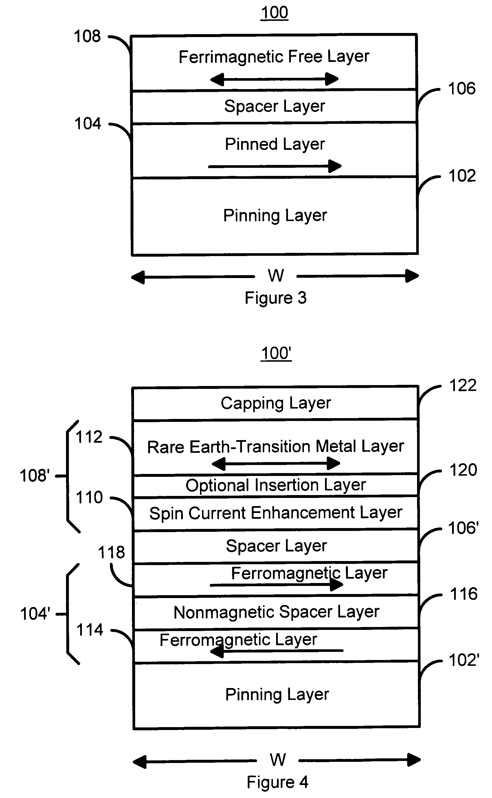
[0024]FIG. 3 is a diagram of a magnetic element 100 in accordance with the present invention and which can be written using spin transfer. The magnetic element 100 includes a pinning layer 102 that is preferably an AFM layer, pinned layer 104, a spacer layer 106, and a free layer 108 that is ferrimagnetic. In an alternate embodiment, the pinning layer 102 may be omitted in favor of another mechanism for pinning the magnetizations of the pinned layer 104. In a preferred embodiment, the AFM layer 102 includes materials such as PtMn and IrMn which have a high blocking temperature, above two hundred degrees Celsius. In addition, one or more seed layers (not shown) may be used to provide a desired texture of the AFM layer 102. The pinned layer 104 may be a simple layer, for example composed of a ferromagnetic alloy including Co, Fe, or Ni. Additives such as B and / or Ta may optionally be added to modify the structure of the pinned layer 104. The pinned layer 104 may also be a synthetic pi...

second embodiment

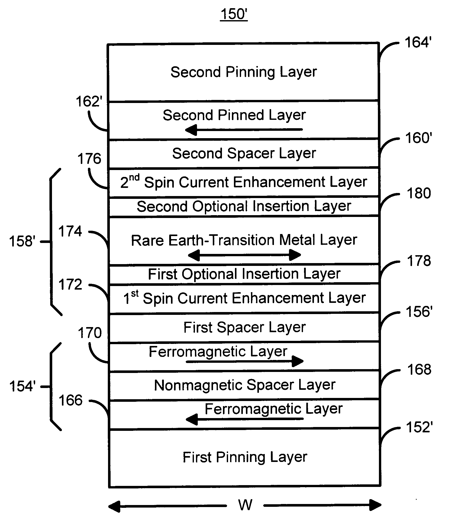
[0044]FIG. 5 is a diagram of a magnetic element 150 in accordance with the present invention and which can be written using spin transfer. Portions of the magnetic element 150 are analogous to the magnetic element 100. However, the magnetic element 150 is a dual structure including two pinned and two spacer layers. The magnetic element 150 includes a first pinning layer 152 that is preferably an AFM layer, a first pinned layer 154, a first spacer layer 156, a free layer 158 that is ferrimagnetic, a second spacer layer 160, a second pinned layer 162, and a second pinning layer 164. In an alternate embodiment, one or more of the pinning layers 152 and 164 may be omitted in favor of another mechanism for pinning the magnetizations of the pinned layers 154 and 162. In a preferred embodiment, the AFM layers 152 and 164 include materials such as PtMn and IrMn which have a high blocking temperature. In addition, one or more seed layers (not shown) may be used to provide a desired texture o...


PUM

PropertyMeasurementUnit
thicknessaaaaaaaaaa
thicknessaaaaaaaaaa
blocking temperatureaaaaaaaaaa

Abstract

A method and system for providing a magnetic element are disclosed. The method and system include providing a pinned layer, providing a spacer layer, and providing a free layer. The free layer is ferrimagnetic and includes at least one of a conductive ferrite, a garnet, a ferrimagnetic alloy excluding a rare earth, a heavy rare-earth-transition metal alloy, a half-metallic ferrimagnetic, and a bilayer. The bilayer includes a rare earth-transition metal alloy layer and a spin current enhancement layer. The magnetic element is configured to allow the free layer to be switched due to spin transfer when a write current is passed through the magnetic element.

Description

FIELD OF THE INVENTION[0001]The present invention relates to magnetic memory systems, and more particularly to a method and system for providing a magnetic element that can be switched using a spin transfer effect at a lower switching current and magnetic memories using the magnetic element.BACKGROUND OF THE INVENTION[0002]FIGS. 1 and 2 depict conventional magnetic elements 10 and 10′. Such conventional magnetic elements 10 / 10′ can be used in non-volatile memories, such as magnetic random access memories (MRAM). The conventional magnetic element 10 is a spin valve and includes a conventional antiferromagnetic (AFM) layer 12, a conventional pinned layer 14, a conventional nonmagnetic spacer layer 16 and a conventional free layer 18. Other layers (not shown), such as seed or capping layer may also be used. The conventional pinned layer 14 and the conventional free layer 18 are ferromagnetic. Thus, the conventional free layer 18 is depicted as having a changeable magnetization 19. The ...

Claims


Application Information

Patent Timeline
Patent Type & Authority Patents(United States)
IPC IPC(8): G11C11/00
CPCB82Y25/00G11C11/16H01F10/3254H01F10/3281H01L43/08H01L43/10H01F10/1936H01F10/3259H01F10/3272H01F10/3263G11C11/161H10N50/10H10N50/85G11C11/15
Inventor PAKALA, MAHENDRACHEN, EUGENE YOUJUNHUAI, YIMING
Owner SAMSUNG SEMICON
Why Eureka
Try Eureka