Device and method of controlling exhaust gas sensor temperature, and recording medium for exhaust gas sensor temperature control program

a technology of exhaust gas sensor and temperature control, which is applied in the direction of electrical control, process and machine control, instruments, etc., can solve the problems of damage to the heater and the active element, the difficulty of stably controlling the temperature of the active element of the exhaust gas sensor at a desired temperature, etc., and achieves the effect of stably controlling, increasing the stability of the temperature of the active element, and stably controlling

Inactive Publication Date: 2009-02-17
HONDA MOTOR CO LTD
View PDF21 Cites 20 Cited by
  • Summary
  • Abstract
  • Description
  • Claims
  • Application Information

AI Technical Summary

Benefits of technology

[0011]Furthermore, a recording medium storing a temperature control program for an exhaust gas sensor according to the present invention is a recording medium readable by a computer and storing a temperature control program for enabling the computer to perform a process of controlling the temperature o an active element of an exhaust gas sensor disposed in an exhaust passage of an internal combustion engine and having the active element for contacting an exhaust gas flowing through the exhaust passage and a heater for heating the active element. According to the first aspect of the present invention, a recording medium storing a temperature control program for an exhaust gas sensor is characterized in that the temperature control program includes a program for enabling the computer to perform a process of sequentially acquiring element temperature data representing the temperature of the active element and heater temperature data representing the temperature of the heater, a control input generating program for enabling the computer to perform a process of sequentially generating a control input which defines an amount of heat generating energy supplied to the heater so as to equalize the temperature of the active element represented by the element temperature data to a predetermined target temperature, and a program for enabling the computer to perform a process of controlling the heater depending on the control input, wherein the control input generating program has an algorithm for enabling the computer to generate the control input so as to include at least an input component depending on the difference between the temperature of the active element represented by the element temperature data and the target temperature and an input component depending on the temperature of the heater represented by the heater temperature data. According to the first aspect of the present invention, since the heater is controlled based on a control input (a manipulated variable for an object to be controlled) including an input component depending on the difference between the temperature of the active element represented by the element temperature data and the target temperature and an input component depending on the temperature of the heater represented by the heater temperature data, or stated otherwise, a control input generated by combining at least the above input components, when the temperature of the active element varies with respect to the target temperature, it is possible to converge the temperature of the active element to the target temperature while suppressing excessive variations of the control input which defines an amount of heat generating energy supplied to the heater. As a result, the temperature of the active element of the exhaust gas sensor can stably be controlled at the target temperature.
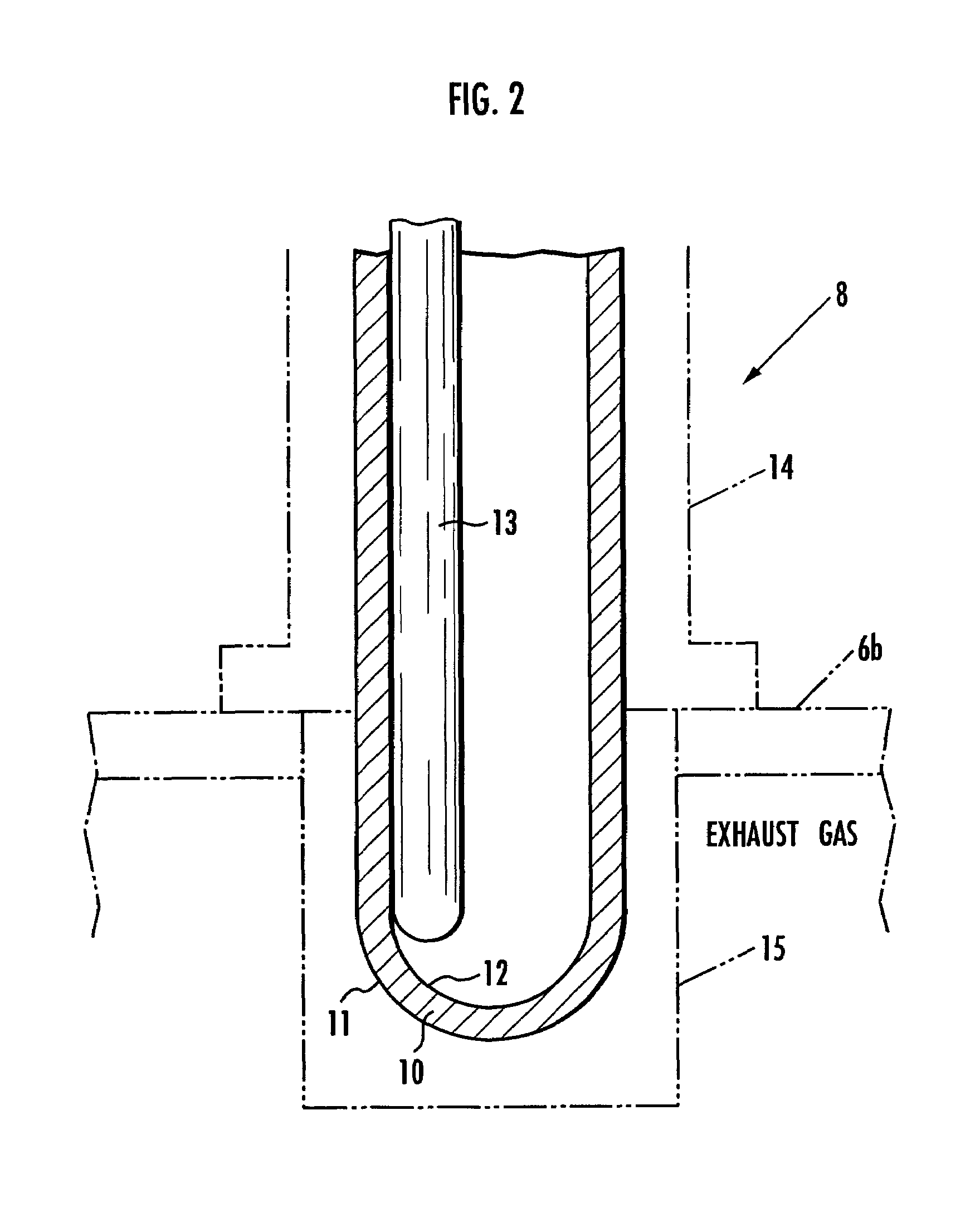
[0101]According to the present invention, the exhaust gas sensor may comprise an O2 sensor disposed downstream of a catalytic converter for purifying the exhaust gas, for example. If the air-fuel ratio of the exhaust gas is controlled to keep the output voltage of the O2 sensor at a predetermined level in order for the catalytic converter to perform its desired exhaust gas purifying capability, the temperature of the active element of the O2 sensor should preferably basically be controlled at a temperature equal to or higher than 750° C. (e.g., 800° C.) for better air-fuel ratio control. In this case, when the heater is to be controlled with a target temperature determined for the active element, the target temperature may be set to a temperature equal to or higher than 750° C. (e.g., 800° C.). When the heater is to be controlled with a target temperature determined for the heater, the target temperature may be set to a temperature equal to or higher than 850° C. (e.g., 900° C.).

Problems solved by technology

According to the disclosure of the above publication, however, since a duty cycle which determines the electric power to be supplied to the heater is uniquely determined by a table from an estimated value of the temperature of the active element of the exhaust gas sensor, it is difficult to control the temperature of the active element of the exhaust gas sensor stably at a desired temperature because of a change in the temperature of the exhaust gas, an ambient air temperature, etc.
Furthermore, if the temperature of the active element of the exhaust gas sensor is low, then in order to keep the duty cycle of the heater at a certain maximum level, the heater tends to consume more electric power than required and the actual temperatures of the heater and the active element are liable to be excessively high, causing damage to the heater and the active element.

Method used


Image

  • Device and method of controlling exhaust gas sensor temperature, and recording medium for exhaust gas sensor temperature control program
  • Device and method of controlling exhaust gas sensor temperature, and recording medium for exhaust gas sensor temperature control program
  • Device and method of controlling exhaust gas sensor temperature, and recording medium for exhaust gas sensor temperature control program

Examples


Embodiment Construction

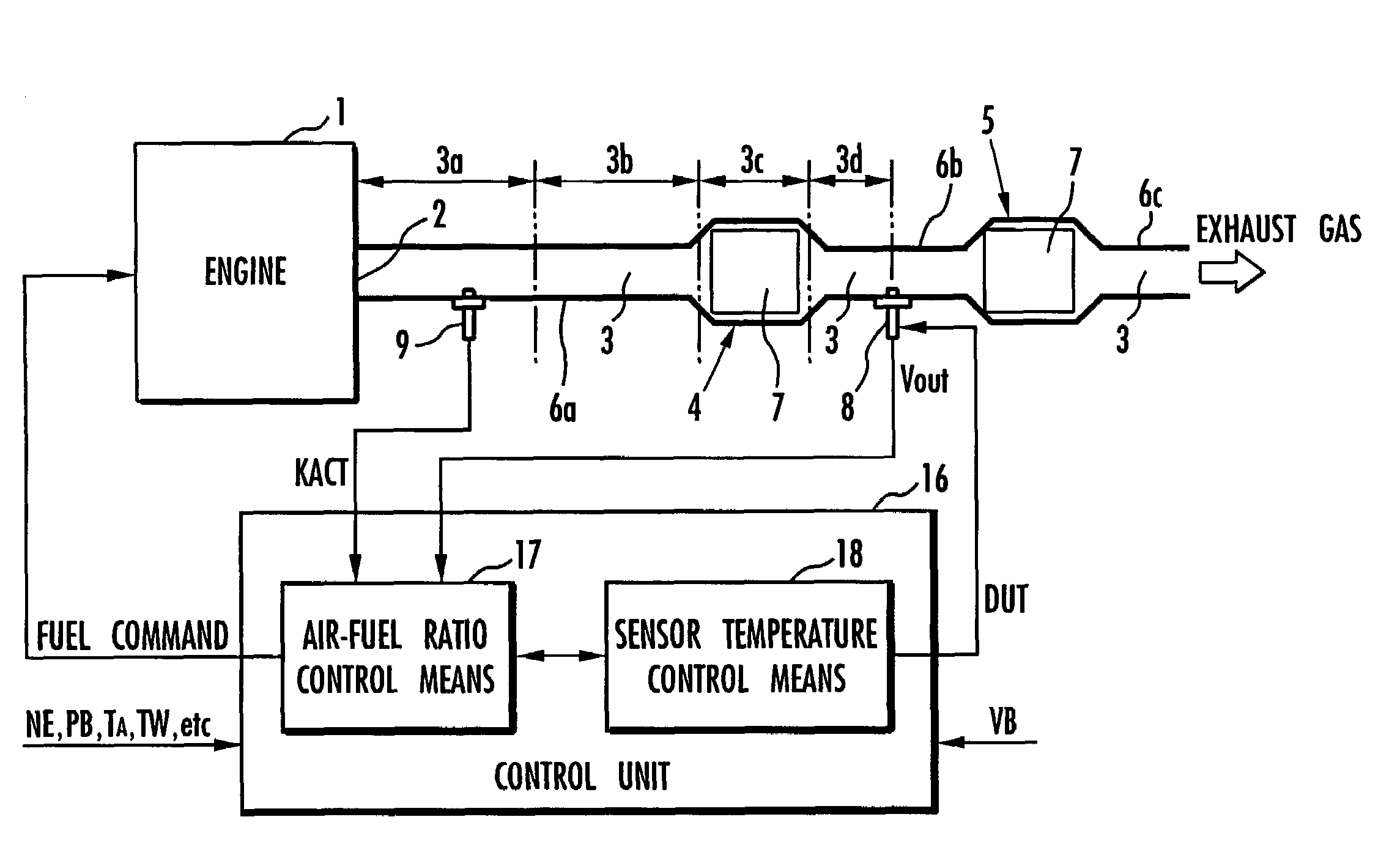
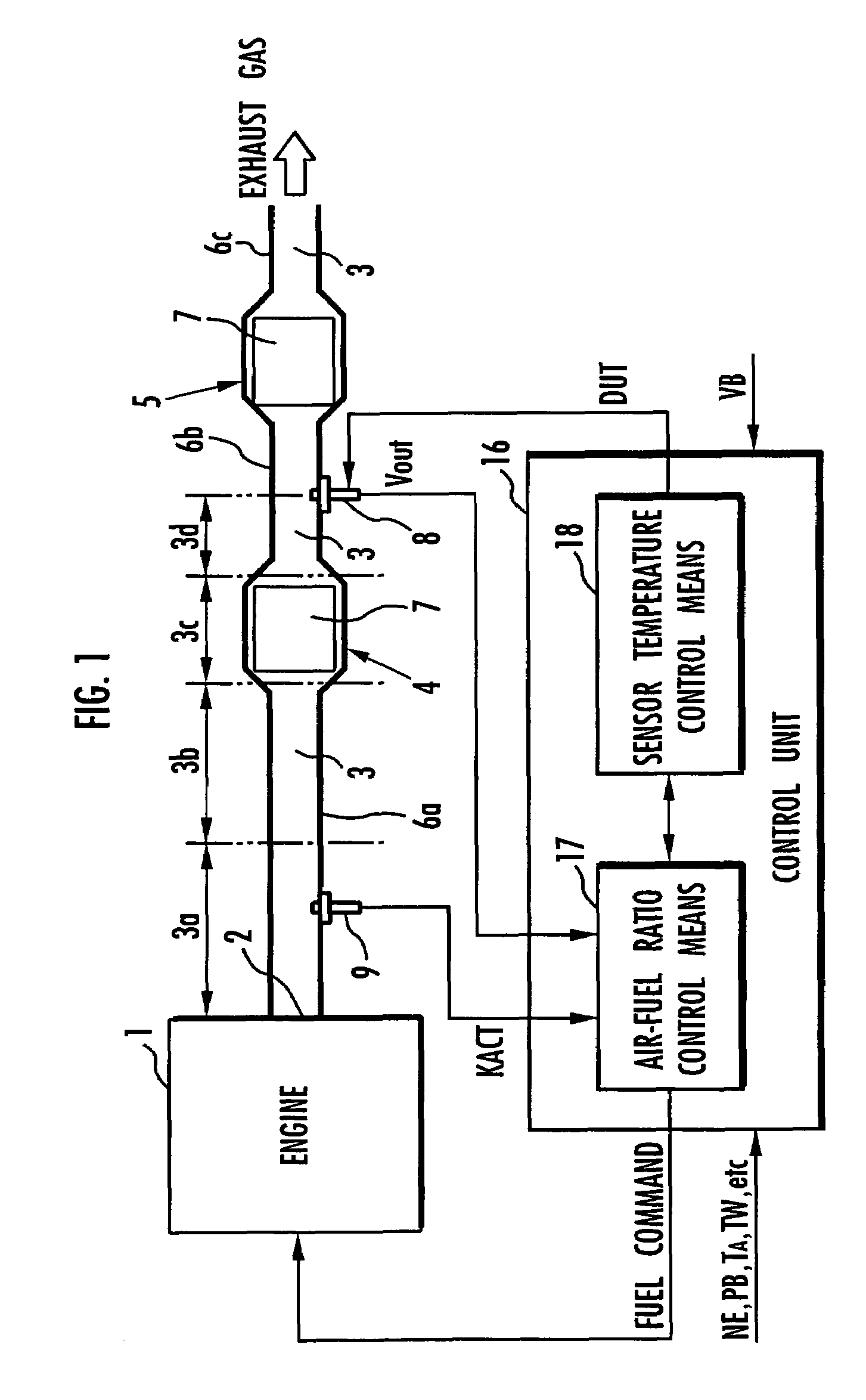
[0114]A first embodiment of the present invention will be described below with reference to FIGS. 1 through 13. FIG. 1 shows in block form an overall arrangement of the apparatus according to the first embodiment of the present invention. In FIG. 1, an engine (an internal combustion engine) 1 mounted on an automobile, a hybrid vehicle, or the like combusts a mixture of fuel and air and generates an exhaust gas, which is discharged into the atmosphere through an exhaust passage 3 communicating with an exhaust port 2 of the engine 1. The exhaust passage 3 incorporates therein two catalytic converters 4, 5 disposed successively downstream for purifying the exhaust gas emitted from the engine 1 and flowing through the exhaust passage 3. The exhaust passage 3 includes a section upstream of the catalytic converter 4 (between the exhaust port 2 and the catalytic converter 4), a section between the catalytic converters 4, 5, and a section downstream of the catalytic converter 5. These secti...


PUM

PropertyMeasurementUnit
temperatureaaaaaaaaaa

Abstract

A control input (DUT) for controlling a heater (13) which heats an active element (10) of an exhaust gas sensor (8) includes at least one of another component depending on the difference between temperature data of the active element (10) and a target temperature, a component depending on the target temperature, and a component depending on the temperature data of the active element (10). The control input is determined by an optimum control algorithm. A component depending on the temperature of an exhaust gas and the component depending on the target temperature are determined based on a predictive control algorithm. The temperature of the active element (10) of the exhaust gas sensor (8) is thus controlled stably at a desired temperature.

Description

TECHNICAL FIELD[0001]The present invention relates to an apparatus for and a method of controlling the temperature of an exhaust gas sensor disposed in the exhaust passage of an internal combustion engine, and a recording medium storing a program for controlling the temperature of such an exhaust gas sensor.BACKGROUND ART[0002]Exhaust gas sensors are often disposed in the exhaust passages of internal combustion engines for detecting a physical quantity as to an exhaust gas component state, such as an exhaust gas component concentration, for the purpose of controlling the operation of the internal combustion engine or monitoring the status of an exhaust gas purifying system. Specifically, the exhaust gas sensor is disposed at a certain location in the exhaust gas passage and has an element sensitive to an exhaust gas component state to be detected, the element being positioned for contact with an exhaust gas flowing through the exhaust passage. For example, an air-fuel ratio sensor s...

Claims


Application Information

Patent Timeline
Patent Type & Authority Patents(United States)
IPC IPC(8): F02D41/00F02D35/00G01N27/409F02D41/14G01N27/406G05D23/19G05D23/24
CPCG01N27/4067G05D23/2401
Inventor YASUI, YUJIIWAKI, YOSHIHISA
Owner HONDA MOTOR CO LTD
Why Eureka
Try Eureka