Graft anchoring device

a technology of graft and anchoring device, which is applied in the field of medical grafting implements, can solve the problems of unnecessary complexity and difficulties of the devices proposed and utilized to date, the risk of damaging or severing the graft and/or suture used, and the system and device in use today for anchoring such graft segments

Inactive Publication Date: 2009-02-17
UNIVERSAL TECH
View PDF18 Cites 123 Cited by
  • Summary
  • Abstract
  • Description
  • Claims
  • Application Information

AI Technical Summary

Benefits of technology

[0017]Another embodiment of the graft anchoring apparatus of the present invention includes a suture guide member having one or more first suture channels extending axially therethrough, and a first mating structure disposed therewith. The apparatus further includes a suture fixing member having one or more second suture channels extending axially therethrough, and a suture lock mechanism disposed adjacent to respective ones of the second suture channels. The suture fixing member further includes a second mating mechanism that is configured for mating engagement with the first mating structure, with such mating engagement operably causing the first and second suture channels to be in respective axial alignment with one another, such that a first end of a graft suture may operably pass through respective first and second suture channels and be secured to the suture fixing member at the suture lock mechanism.
[0018]In another embodiment, the graft anchoring device of the present invention includes a substantially frusto-conical fastener device having a proximal portion and a distal portion. The fastener device is preferably configured such that the diameter at a distal end thereof is relatively smaller then the diameter at a proximal end thereof. The fastener device is threadably inserted and secured in a respective specifically configured graft channel in a fixed structure. The fastener device further includes an open bore axially extending therethrough, with a portion of the open bore at the distal portion of the fastener device being divided into a plurality of distinct suture pathways by a divider, such that individual graft sutures may be operably passed through respective distinct suture pathways so as to prevent the graft sutures from inter-winding about one another at the distal portion of the fastener device during the threadable insertion of the fastener device into the graft channel.
[0019]A still further embodiment of the graft anchoring apparatus of the present invention includes one or more suture receiving members each having one or more suture receptacles disposed therein, and a displacement member that is specifically configured to matingly engage with the one or more suture receiving members. The mating engagement between the displacement member and the one or more suture receiving members operably compresses the one or more suture receptacles in the one or more suture receiving members to thereby frictionally secure one or more graft sutures within respective ones of the suture receptacles.

Problems solved by technology

The devices proposed and utilized to date, however, have drawbacks associated with their design or implementation in vivo.
In particular, systems and devices in use today for anchoring such graft segments introduce unnecessary complexities and difficulties during a surgical grafting procedure.
For example, currently used interference screws which bias a graft segment or suture therefore against a wall of a channel bored into or through a respective fixed structure introduce a risk of damaging or severing the graft and / or suture used to secure the graft material to the anchoring structure.
Such damage or severing can result in surgical failure.
Other known anchoring devices require specialized operating room equipment, and do not provide adequate error tolerances in their application.
A particular deficiency in current devices is the failure to provide a means for readily altering the suture length or tension in vivo to thereby optimize graft material fit during the surgical process.

Method used


Image

  • Graft anchoring device
  • Graft anchoring device
  • Graft anchoring device

Examples


Embodiment Construction

[0047]The objects and advantages enumerated above together with other objects, features, and advances represented by the present invention will now be presented in terms of detailed embodiments described with reference to the attached drawing figures which are intended to be representative of various possible configurations of the invention. Other embodiments and aspects of the invention are recognized as being within the grasp of those having ordinary skill in the art.

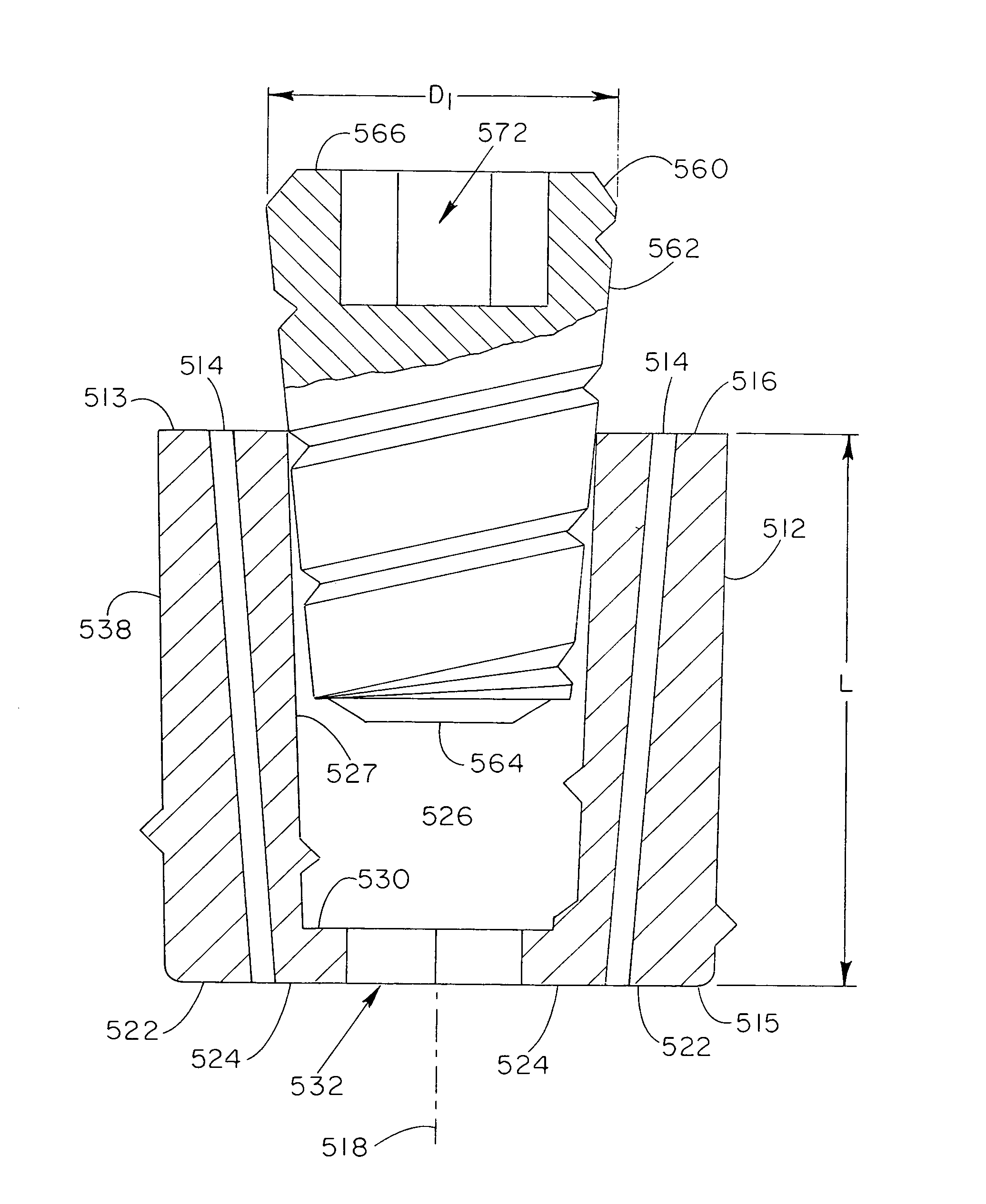
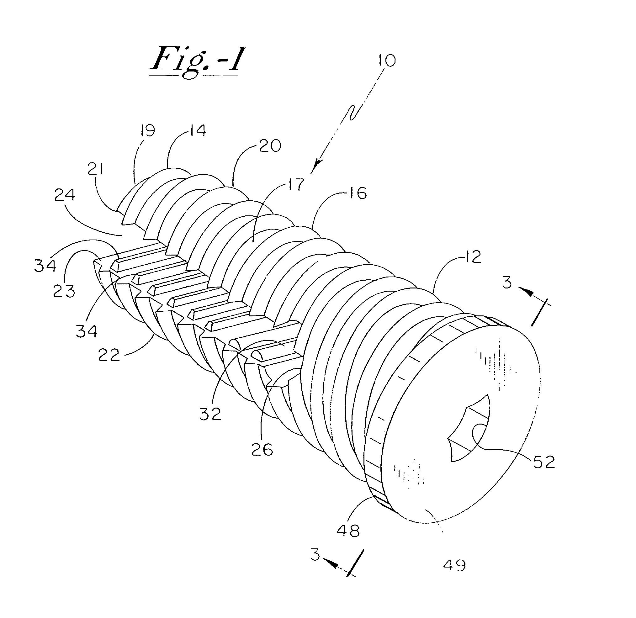
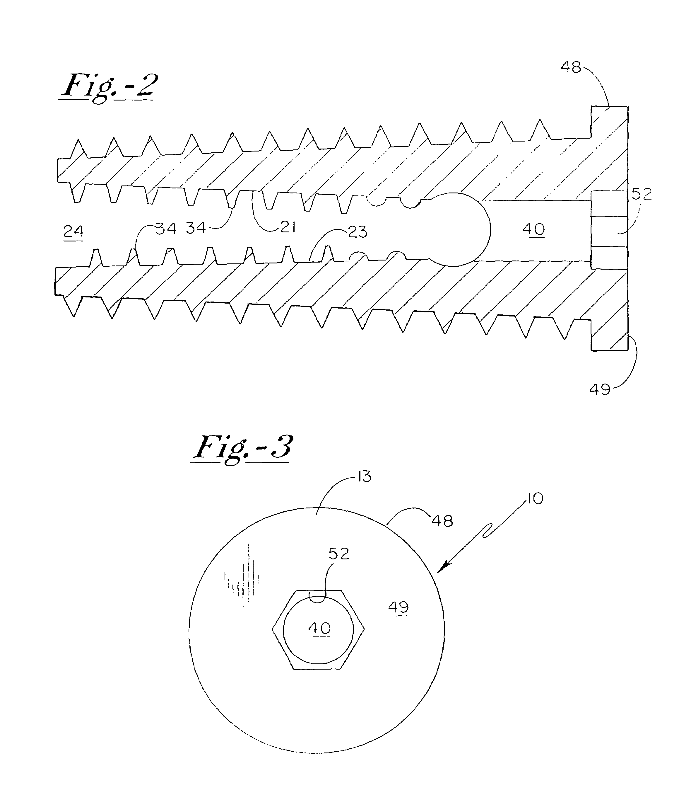
[0048]With attention now to the drawings, and first to FIG. 1, a graft anchoring device 10 is shown in perspective view. Anchoring device 10 is preferably substantially cylindrical, and most preferably includes a taper such that distal portion 14 has a diameter smaller than that of proximal portion 12 thereof. Such a configuration may be termed frusto-conical. As shown in FIG. 1, anchoring device 10 preferably includes threads 16 on an outer surface 17 thereof, which threads 16 are preferably configured in a 60 degree...


PUM


Abstract

An apparatus for anchoring a graft segment to a fixed structure in-vivo includes a sleeve member having one or more suture channels extending axially therethrough and an axial opening extending adjacent to the one or more suture channels from a first end of the sleeve member. The apparatus further includes a plug member that is configured for mating engagement within the axial opening of the sleeve member, with such engagement compressing the one or more suture channels to frictionally secure a respective graft suture therein.

Description

CROSS REFERENCE TO RELATED APPLICATIONS[0001]The present application is a continuation-in-part of application Ser. No. 10 / 741,686, filed Dec. 19, 2003 now abandoned, and entitled “GRAFT ANCHORING DEVICE”, which itself is a continuation-in-part of application Ser. No. 10 / 271,923, filed Oct. 16, 2002 now abandoned, entitled “GRAFT ANCHORING DEVICE”, which claims priority from provisional patent application Ser. No. 60 / 330,002, filed Oct. 16, 2001, and entitled “GRAFT ANCHORING DEVICE”, the contents of such applications being incorporated herein in their entirety.FIELD OF THE INVENTION[0002]The present invention relates to medical grafting implements generally, and more particularly to graft anchoring devices for anchoring grafted material segments to bones or other fixed structures in the body. The present invention also relates to methods for anchoring graft segments to adjacent structures.BACKGROUND OF THE INVENTION[0003]In vivo grafting procedures have been successfully performed f...

Claims


Application Information

Patent Timeline
Patent Type & Authority Patents(United States)
IPC IPC(8): A61B17/04
CPCA61B17/0401A61F2/0811A61B2017/0425A61B2017/0438A61B2017/044A61B2017/045A61B2017/0453A61B2017/0456A61B2017/0458A61F2002/0882
Inventor HENDREN, RONALD D.PUTNAM, MATTHEW D.
Owner UNIVERSAL TECH
Why Eureka
Try Eureka