
Drum shell mounting system and associated methods

a drum shell and mounting system technology, applied in the field of drum shell mounting systems and associated methods, can solve the problems of less than desirable practice and difficult alignment and tuning of prior art systems

Inactive Publication Date: 2009-02-17
CHERNY MICHALE N
View PDF16 Cites 11 Cited by
  • Summary
  • Abstract
  • Description
  • Claims
  • Application Information

AI Technical Summary

Benefits of technology

[0015]The features that characterize the invention, both as to organization and method of operation, together with further objects and advantages thereof, will be better understood from the following description used in conjunction with the accompanying drawing. It is to be expressly understood that the drawing is for the purpose of illustration and description and is not intended as a definition of the limits of the invention. These and other objects attained, and advantages offered, by the present invention will become more fully apparent as the description that now follows is read in conjunction with the accompanying drawing.

Problems solved by technology

This is believed to be a less than desirable practice, since such direct contact dampens the shell's vibration and its resonance.
However, the prior art systems are difficult to align and tune.

Method used


Image

  • Drum shell mounting system and associated methods
  • Drum shell mounting system and associated methods
  • Drum shell mounting system and associated methods

Examples


Embodiment Construction

[0024]A description of the preferred embodiments of the present invention will now be presented with reference to FIGS. 1-8.

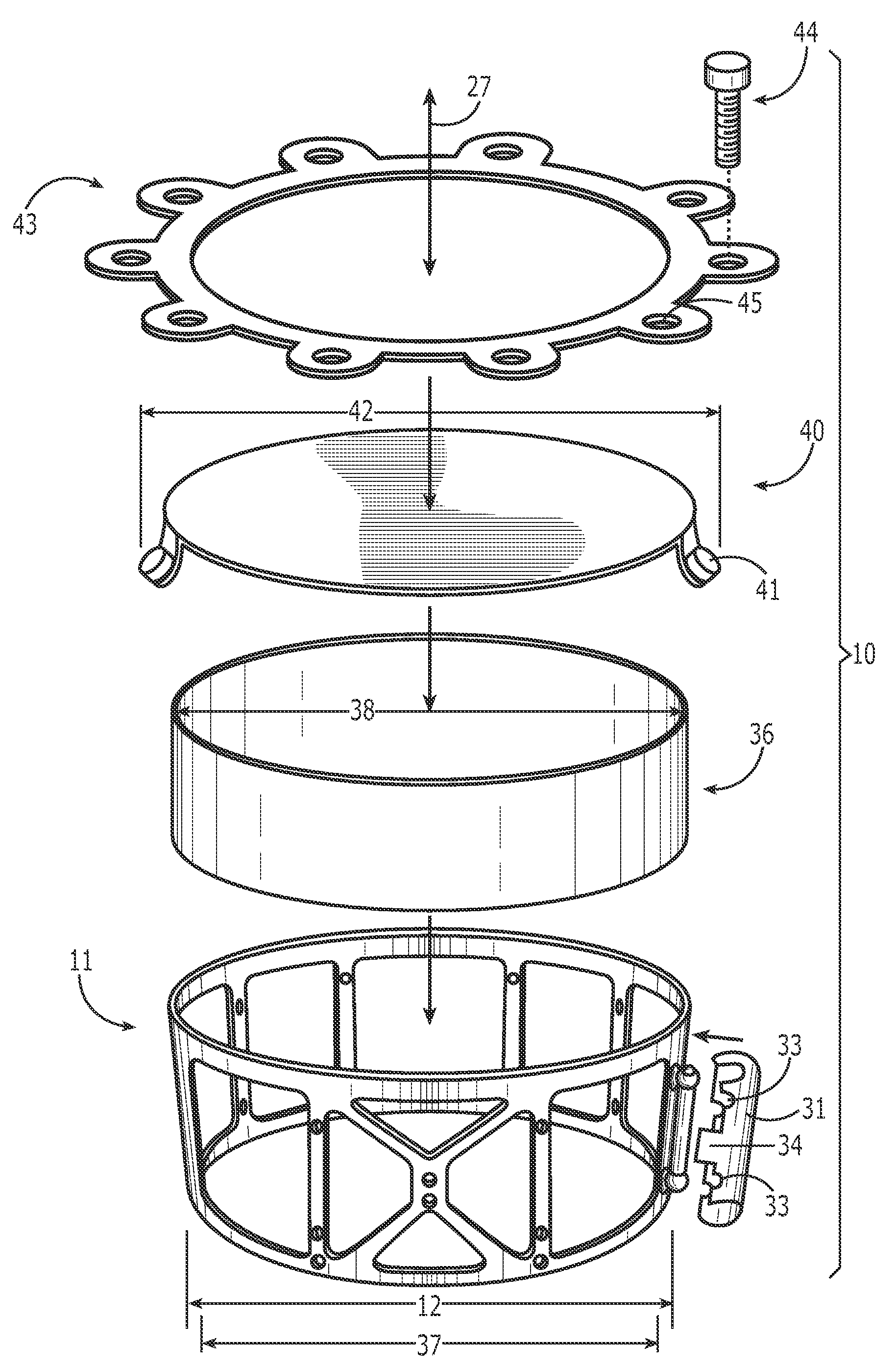
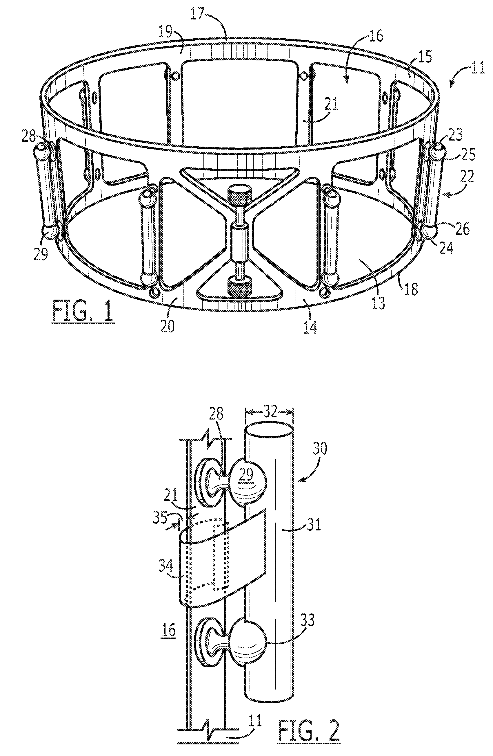
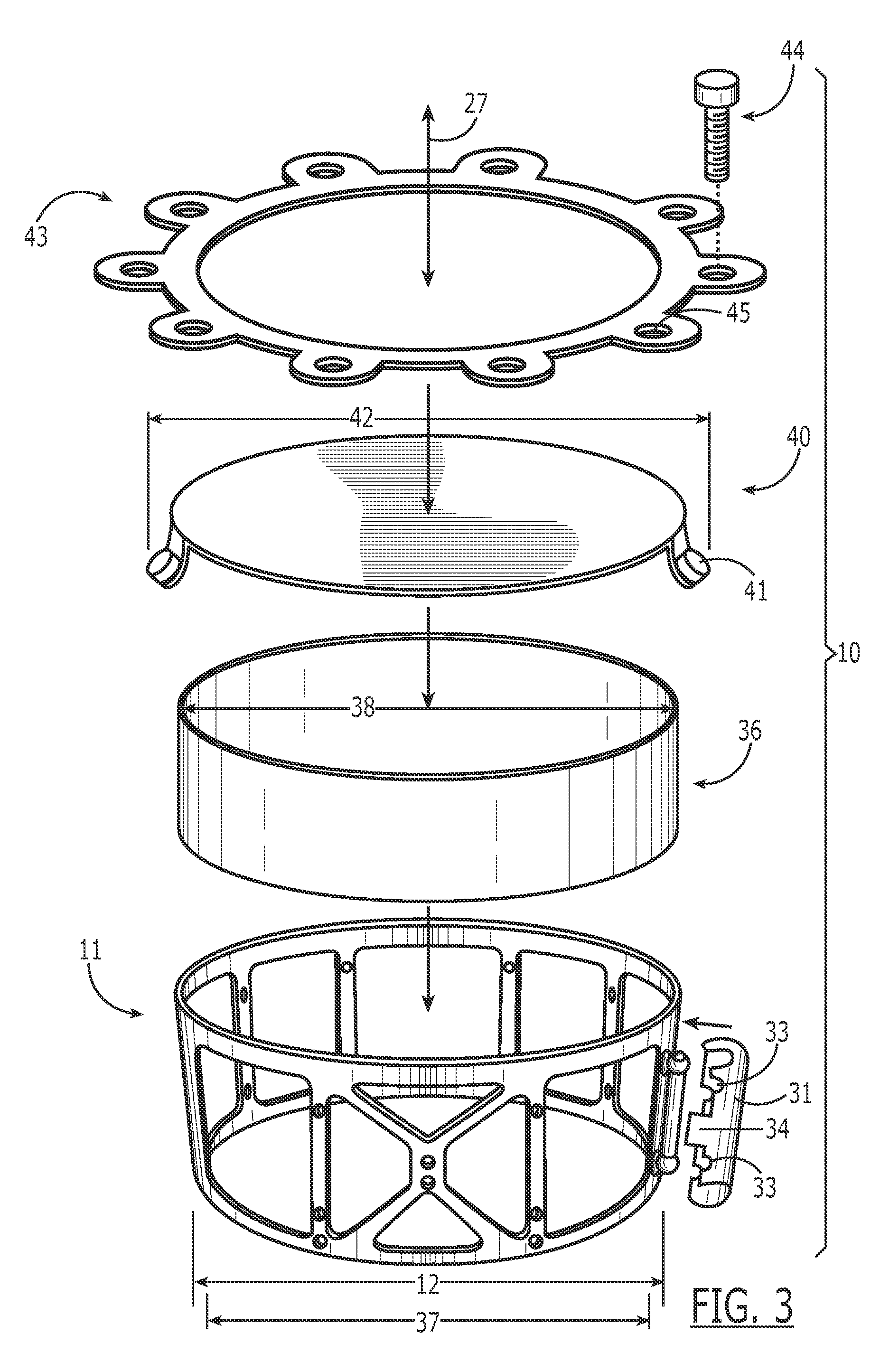
[0025]The present invention is directed to a drum shell mounting system 10 (FIGS. 1-4) that comprises a generally cylindrical cage 11 (FIG. 1) that has an outer diameter 12. At least one, a preferably a plurality of, windows 13 extend from an outer face 14 through to an inner face 15 of the cage 11. The cage 11 has a bore 16 therethrough from a top edge 17 to a bottom edge 18. In a preferred embodiment, the windows 13 comprise a greater surface area than the solid material of the cage 11, leaving an upper rim portion 19 beneath the top edge 17 and a lower rim portion 20 above the bottom edge 18, with cross-pieces 21 extending therebetween to define the windows 13.

[0026]Extending outward from the cage's outer face 14 is a plurality of posts 22, here 10 posts, in circumferentially spaced relation therearound. The posts 22 in a preferred embodiment are equal in nu...


PUM


Abstract

A drum shell mounting system includes a cylindrical cage that has an outer diameter less than a drum head diameter and a plurality of windows. The cage's bore is larger than the drum shell's. A plurality of posts extend outwardly and have apertures for receiving fasteners. Removably affixable mounting clips extend into the cage's bore. In use, drum assembly proceeds by affixing the mounting clip to the cage and inserting the drum head into the cage's bore. A spacing between the cage's inner face and the drum head is maintained by the mounting clip, the drum head is placed atop the cage with a rim of the drum head positioned outside a top edge of the cage, a hoop is placed around the drum head, fasteners are inserted through hoop apertures and into the post apertures to secure the head, and the mounting clips are removed.

Description

CROSS-REFERENCE TO RELATED APPLICATION[0001]This application claims priority to provisional application Ser. No. 60 / 804,337, filed Jun. 9, 2006.BACKGROUND OF THE INVENTION[0002]1. Field of the Invention[0003]The present invention relates to systems and methods for percussion instruments, and, more particularly, to such systems and methods for mounting drum shells.[0004]2. Description of Related Art[0005]Conventional drums are known to comprise a generally cylindrical shell with a drum head affixed at least one end, for example, with the use of a rim. In such a system, the head thereby is in direct contact with the shell, and the shell is typically bored through to permit access by the attachment means. This is believed to be a less than desirable practice, since such direct contact dampens the shell's vibration and its resonance. Therefore, attempts have been made in the art to eliminate this direct attachment and drilling of holes in the shell by encasing free-floating drum shells ...

Claims


Application Information

Patent Timeline
Patent Type & Authority Patents(United States)
IPC IPC(8): G10D13/02
CPCG10D13/02G10D13/028G10D13/22
Inventor CHERNY, MICHALE N.
Owner CHERNY MICHALE N
Learn More