
Stake assembly for animal traps

Inactive Publication Date: 2007-10-16
BOLSTAD DUANE
View PDF7 Cites 2 Cited by
  • Summary
  • Abstract
  • Description
  • Claims
  • Application Information

AI Technical Summary

Benefits of technology

[0011]In view of the foregoing background, it is therefore an object of the present invention to provide a stake assembly for animal traps. These and other objects, features, and advantages of the invention are provided by a ground anchoring stake assembly for effectively securing animal traps to a ground surface.
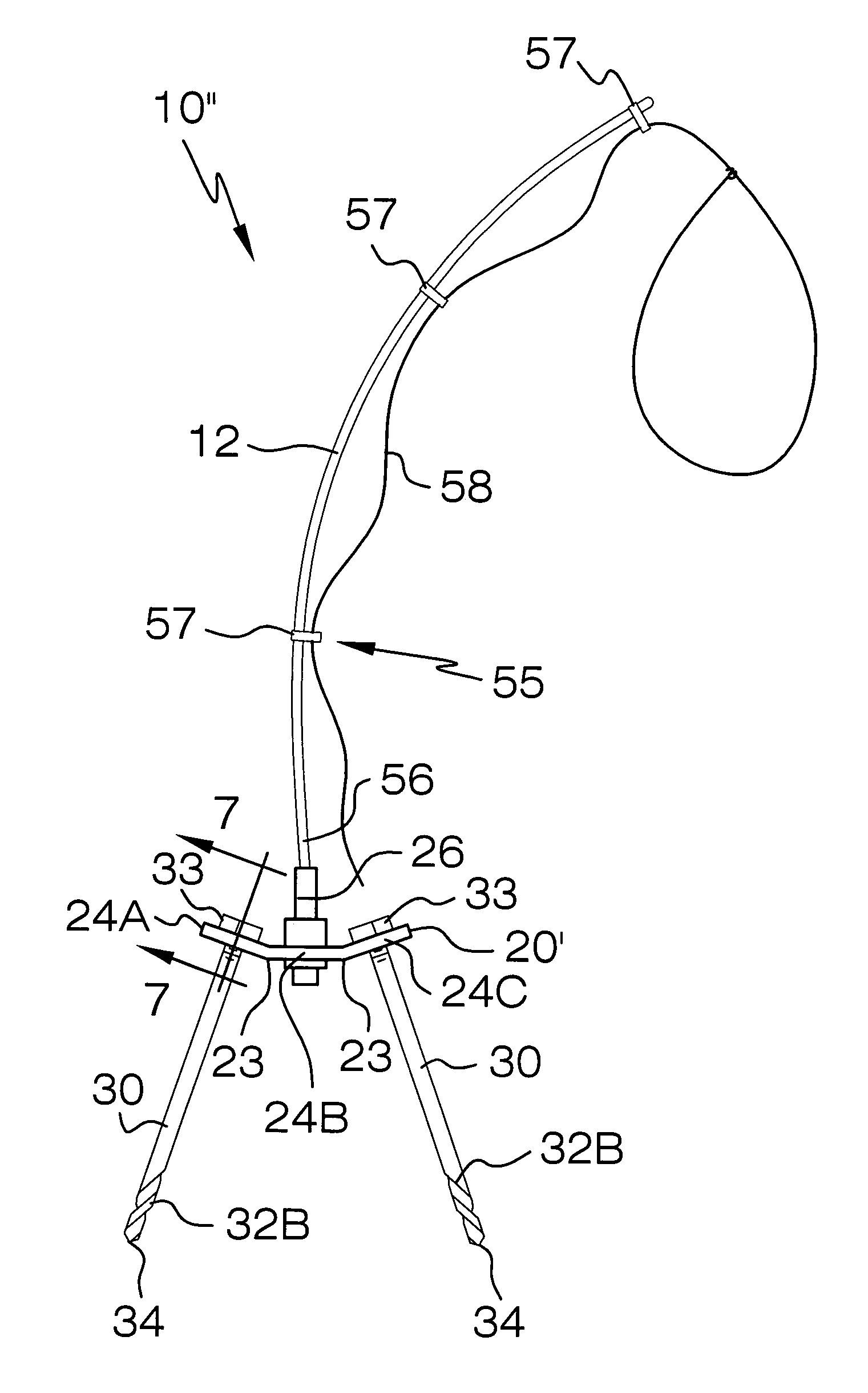
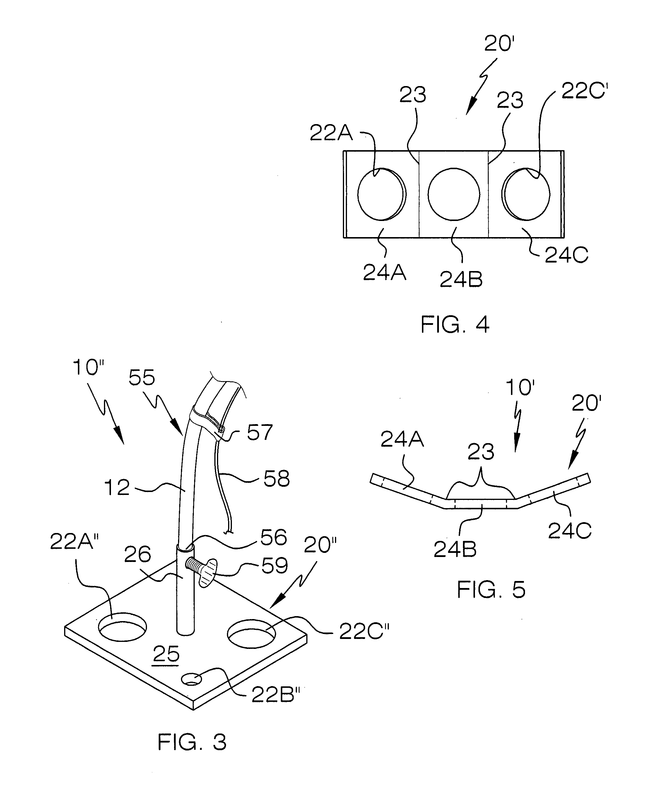
[0013]In an alternate embodiment, the anchor plate preferably includes a plurality of linear creases traversing the axis and equidistantly spaced along a longitudinal length thereof. Such an anchor plate further includes a plurality of monolithically formed and coextensively shaped sections separated by the creases. The apertures including first, second and third apertures centrally registered within the sections wherein the first and third sections are beveled upwardly and outwardly away from the second section such that the second section rests directly on the ground surface while the first and third sections flange upwardly away from the ground surface. The first and third sections preferably laterally diverge from the second section at an oblique angle defined less than 90 degrees measured from the ground surface. The at least one stake includes first and second stakes independently passed through the first and third apertures for securely maintaining the anchor plate engaged with the ground surface during operating conditions.
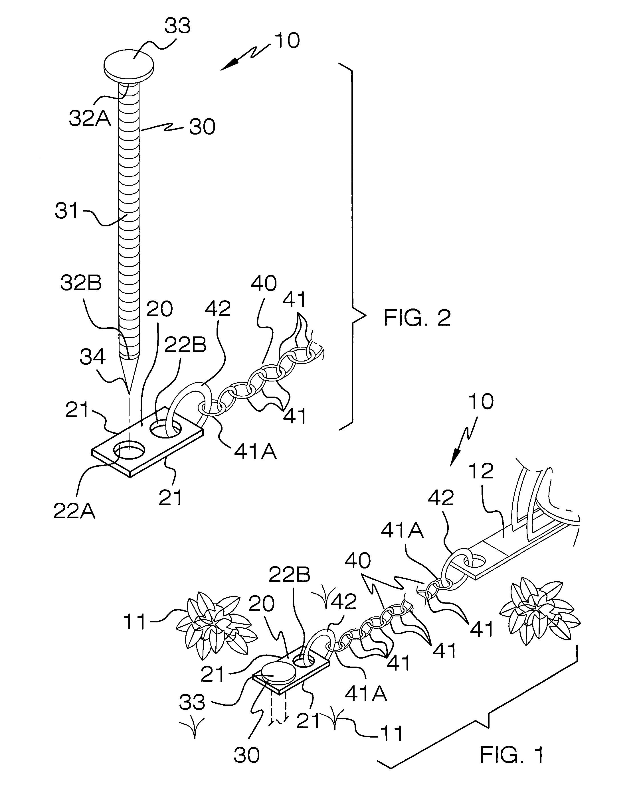
[0015]At least one elongated stake is removably inserted through at least one of the apertures and directly interfitted into the ground surface in such a manner that the anchor plate is advantageously and effectively prohibited from being disengaged from the ground surface while the stake is traversed therethrough. Such a stake preferably has a chamfered exterior surface for advantageously and effectively maximizing surface area contact below the ground surface.
[0016]A flexible and elongated chain includes a plurality of substantially annular child links directly connected end-to-end. Such a chain further includes a plurality of parent links that have a greater thickness and a greater diameter than a diameter and a thickness of the child links respectively. The parent links are directly and permanently fastened to another one of the apertures and the animal trap respectively. Such parent links are directly and permanently fastened to outer ones of the child links respectively. The chain is formed from steel. The anchor plate and the at least one stake effectively resist external forces acting on the chain so that the animal trap is advantageously prevented from moving beyond a maximum distance defined by a longitudinal length of the chain.

Problems solved by technology

However, stakes of the prior art suffer from several deficiencies.
First, many prior art stakes do not, of themselves, provide a universal pivoting connection between the stake and the connecting member.
Consequently, the connecting member often becomes tangled or wrapped about the stake.
Of those prior art stakes which do provide such a universal pivoting connection, additional hardware is required, thus increasing the expense and complexity thereof.
Second, most prior art stakes do not readily permit a second stake to be used in a multiple staking arrangement with the first stake.
Multiple staking arrangements are necessary when the device to be anchored might be subject to relatively large forces attempting to withdraw the stake from the ground.

Method used


Image

  • Stake assembly for animal traps
  • Stake assembly for animal traps
  • Stake assembly for animal traps

Examples


Embodiment Construction

[0027]The present invention will now be described more fully hereinafter with reference to the accompanying drawings, in which preferred embodiments of the invention are shown. This invention may, however, be embodied in many different forms and should not be construed as limited to the embodiments set forth herein. Rather, these embodiments are provided so that this application will be thorough and complete, and will fully convey the true scope of the invention to those skilled in the art. Like numbers refer to like elements throughout the figures and prime and double prime numbers refer to alternate embodiments of such elements.

[0028]The assembly of this invention is referred to generally in FIGS. 1-6 by the reference numeral 10 and is intended to provide a stake assembly for animal traps. It should be understood that the assembly 10 may be used to stake many different types of items to ground surfaces and should not be limited in use to only staking animal traps to a ground surfa...


PUM


Abstract

An assembly includes an anchor plate that is formed from steel and has opposing sides spaced from the axis and extends parallel thereto. The anchor plate is further provided with spaced apertures formed therein. One elongated stake is inserted through one aperture and interfitted into the ground so that the anchor plate is prohibited from being disengaged from the ground. A chain includes child links connected end-to-end and parent links having a greater thickness and diameter than the child links. The parent links are fastened to one of the apertures and the animal trap, and are fastened to outer ones of the child links. The chain is formed from steel. The anchor plate and one stake resist external forces acting on the chain so that the animal trap is prevented from moving beyond a maximum distance defined by a length of the chain.

Description

CROSS REFERENCE TO RELATED APPLICATIONS[0001]Not Applicable.STATEMENT REGARDING FEDERALLY SPONSORED RESEARCH OR DEVELOPMENT[0002]Not Applicable.REFERENCE TO A MICROFICHE APPENDIX[0003]Not Applicable.BACKGROUND OF THE INVENTION[0004]1. Technical Field[0005]This invention relates to stake assemblies and, more particularly, to a stake assembly for securing animal traps to a ground surface.[0006]2. Prior Art[0007]Stakes have long been used to securely anchor various types of devices at desired locations in undeveloped areas of ground. Such stakes are generally designed so as to resist the withdrawal thereof from the ground, thereby permitting these devices to be reliably retained therein. Typically, one end of a chain, rope, or similar connecting member is attached to the stake. The other end of the connecting member is attached to the device (which may be an animal trap, tent, and the like), so as to provide a reliable anchor for the device in the ground at that particular location.[00...

Claims


Application Information

Patent Timeline
IPC IPC(8): A01M23/00A01M23/24
CPCA01M23/245
Inventor BOLSTAD, DUANE
Owner BOLSTAD DUANE
Learn More