Filter element with off-axis end cap

a filter element and end cap technology, applied in the field of fluid filters, can solve the problems of reducing the surface area of the media available for filtration, adding cost to the system, and complex manufacturing and assembly, and achieves the effects of reducing the cost of filtration, simple manufacturing and assembly, and fewer components

Active Publication Date: 2009-02-24
PARKER INTANGIBLES LLC
View PDF17 Cites 76 Cited by
  • Summary
  • Abstract
  • Description
  • Claims
  • Application Information

AI Technical Summary

Benefits of technology

[0006]The present invention provides a novel and unique filter, particularly for hydraulic fluid, which has few components, is simple to manufacture and assemble, and includes increased surface area for filtration.
[0008]A support member at the opposite distal end of the container supports the other annular end cap of the filter element. The element can be removed when it is spent from the open end of the head casting after removal of the cover member. A spring tab can be provided on the flange, which is engaged by the cover member to urge the element into fluid tight engagement with an internal ledge in the head. In addition, a handle can be provided in the first end cap of the element to facilitate removal from the head.
[0009]The filter element includes a larger extent of media than in prior designs, as the media can extend up into the head casting, thereby increasing the overall surface area available for filtration.
[0010]As such, the present invention provides a novel and unique filter, particularly for hydraulic fluid, which has few components, is simple to manufacture and assemble, and includes increased surface area for filtration.

Problems solved by technology

While the filter described above has received acceptance in the market and provides a number of benefits for the user, it requires a separate diverter component, which adds cost to the system, complexity in manufacture and assembly, and also reduces the surface area of the media available for filtration.

Method used


Image

  • Filter element with off-axis end cap
  • Filter element with off-axis end cap
  • Filter element with off-axis end cap

Examples


Embodiment Construction

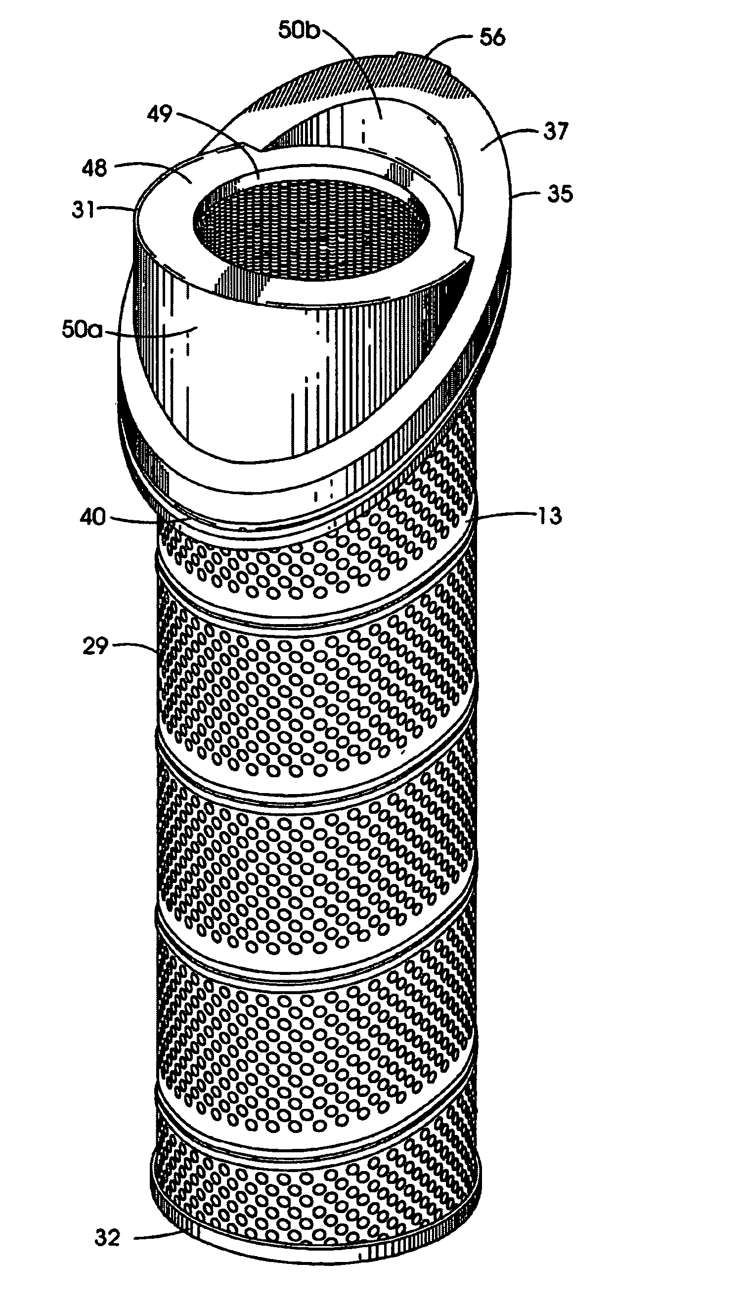
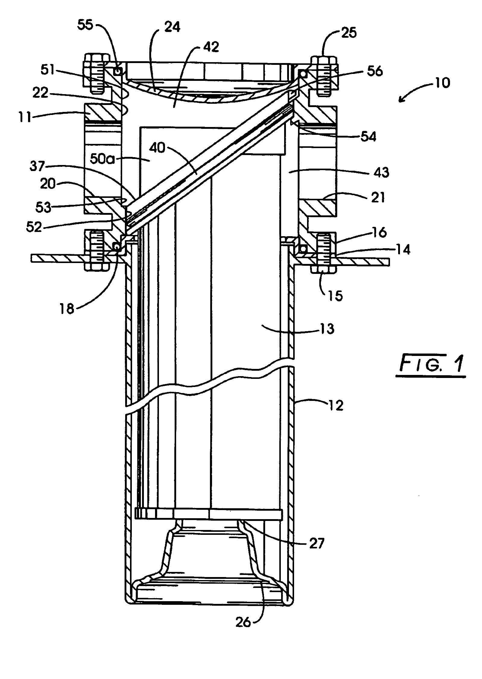
[0019]Referring to the drawings, and initially to FIG. 1, a filter constructed according to the present invention is indicated generally at 10. The filter includes a generally tubular head casting 11 and a tubular filter container 12 which together form an enclosure or housing for a filter element 13. The container 12 includes an annular flange piece 14 at one end welded to the container 12. The flange 14 has arcuate slots therein (not shown) for receipt of mounting bolts 15 engaging threaded holes in a flange portion 16 of the head casting 11 to provide a quick-release fastening arrangement. An O-ring seal 18 between the flanges 14, 16 provides a fluid seal.

[0020]The head casting 11 includes an inlet port 20 and outlet port 21, generally in alignment with one another and both disposed substantially transverse to the longitudinal axis of the tubular housing 12. The head casting 11 comprises a generally cylindrical inner surface 22 extending therethrough, being closed at one end by c...


PUM

PropertyMeasurementUnit
outer dimensionaaaaaaaaaa
oblique angleaaaaaaaaaa
energyaaaaaaaaaa

Abstract

A filter includes a filter element with an enlarged end cap at one end of a media ring with an elliptical flange set oblique or angled to the longitudinal axis of the element. The flange carries a sealing element, and is closely and sealingly received in a head casting of the filter to divide the head casting into inlet and outlet partitions. The end cap directs fluid from a transverse port in the housing into an axial flow path into the central cavity of the element, where the fluid flows radially outward through the media, and then out through an opposite transverse port in the head casting. The element can be removed when it is spent from the head casting after removal of an end closure.

Description

CROSS-REFERENCE TO RELATED CASES[0001]The present application claims the benefit of the filing date of U.S. Provisional Application Ser. No. 60 / 571,775; filed May 17, 2004, the disclosure of which is expressly incorporated herein by reference.BACKGROUND OF THE INVENTION[0002]The present invention relates to fluid filters and more particularly to a hydraulic filter.[0003]Hydraulic filters are commonly used as suction line filters, return line filters and pressure filters. One known filter is shown and described in U.S. Pat. No. 4,272,368, owned by the assignee of the present invention, in which a two piece housing is provided consisting of a head casting and an elongated, tubular filter container. A tubular filter element, having annular end caps sealingly bonded at each end of a ring-shaped media, is removeably located in the container. A diverter structure provides means for separating the head casting into inlet and outlet partitions in fluid communication respectively with the in...

Claims


Application Information

Patent Timeline
Patent Type & Authority Patents(United States)
IPC IPC(8): B01D35/02B01D27/00B01D35/28B01D35/147B01D29/23
CPCB01D35/147B01D29/23B01D2201/295B01D2201/296B01D2201/302B01D2201/34
Inventor MILLER, DANIEL W.
Owner PARKER INTANGIBLES LLC
Why Eureka
Try Eureka