
Systems and methods for identity verification using continuous biometric monitoring

a biometric monitoring and identity verification technology, applied in the field of identity verification, can solve the problems of inmates often attempting to circumvent identity verification procedures, and the authorities rarely know with certainty which inmates actually ar

Active Publication Date: 2009-02-24
SECURUS TECH HLDG
View PDF12 Cites 133 Cited by
  • Summary
  • Abstract
  • Description
  • Claims
  • Application Information

AI Technical Summary

Benefits of technology

Ensures accurate identification of individuals participating in calls, preventing misuse of PINs or biometric features, and allowing for appropriate actions to be taken during ongoing calls, such as termination or recording, thereby enhancing security and compliance with access rules.

Problems solved by technology

Particularly, a problem unique to controlled-environment facilities such as prisons is that inmates frequently attempt to circumvent identity verification procedures.
Consequently, authorities seldom know with certainty which inmate actually participated through the entire course of a phone call, despite the presence of a PIN and / or biometric identity verification procedure.

Method used


Image

  • Systems and methods for identity verification using continuous biometric monitoring
  • Systems and methods for identity verification using continuous biometric monitoring
  • Systems and methods for identity verification using continuous biometric monitoring

Examples


Embodiment Construction

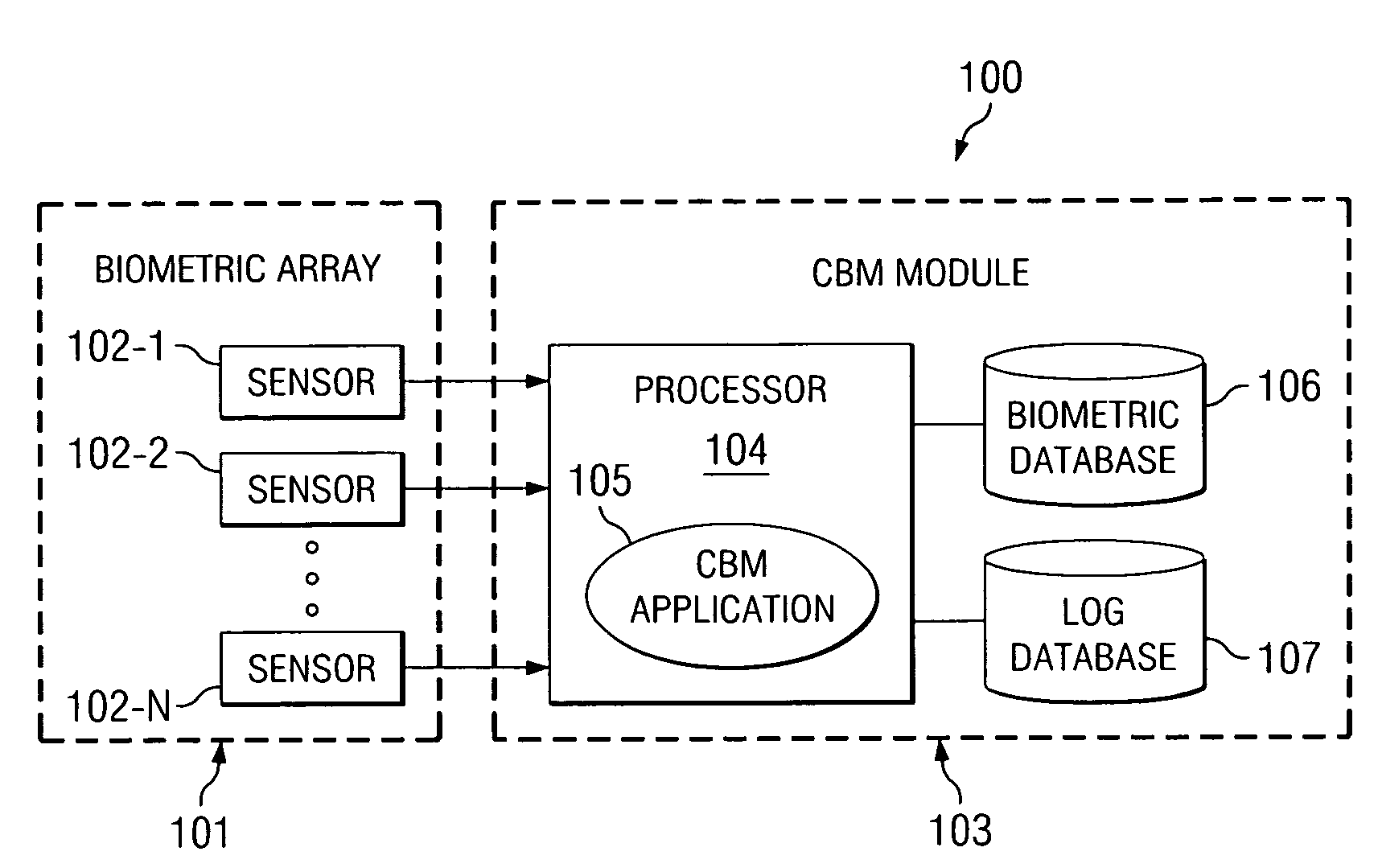
[0020]FIG. 1 is a high-level block diagram of Continuous Biometric Monitoring (CBM) system 100, according to an exemplary embodiment of the present invention. Biometric array 101 may have one or more biometric sensors (or scanners) 102-1, 102-2, . . . , 102-N (collectively “sensors 102”). Each of sensors 102 may be adapted to scan, for example: a physical biometric trait such as a fingerprint, thumbprint, or hand geometry; an aural biometric trait such as a voice or sound; or a visual biometric trait such as a retina, iris, or face. Sensors 102 may be any biometric sensor or scanner now existing or yet to be developed. Sensors 102 are connected to processor 104 of CBM module 103. Processor 104 is operable to execute CBM application 105. Processor 102 is also connected to biometric records database 106 and activity log database 107. According to certain embodiments of the present invention, any one or more of biometric array 101, processor 104, biometric records database 106, and act...


PUM


Abstract

Systems and methods for verifying the identity of a person operating a device are shown. In some representative embodiments, a method comprises authorizing a person to operate a device, continuously monitoring a biometric trait of a device operator, and using the monitored biometric trait of the device operator to verify, during operation of the device, whether the device operator is the authorized person. In other representative embodiments, a system comprises a biometric sensor associated with a device, and a continuous biometric monitoring (CBM) module coupled to the biometric sensor. The CBM module may be adapted to continuously acquire a one biometric sample from the device operator during operation of the device.

Description

RELATED APPLICATIONS[0001]The present application is related to co-pending and commonly assigned U.S. patent applications Ser. No. 10 / 217,149 entitled “SYSTEM AND METHOD FOR CALL TREATMENT;” Ser. No. 10 / 642,532 entitled “CENTRALIZED CALL PROCESSING;” Ser. No. 10 / 701,549 entitled “SYSTEMS AND METHODS FOR CROSS-HATCHING BIOMETRICS WITH OTHER IDENTIFYING DATA;” and Ser. No. 11 / 334,522 entitled “SYSTEM AND METHOD FOR KEYWORD DETECTION IN A CONTROLLED ENVIRONMENT FACILITY USING A HYBRID APPLICATION;” the disclosures of each of which are hereby incorporated herein by reference in their entirety.TECHNICAL FIELD[0002]The present invention relates generally to identity verification, and more particularly, to identity verification using continuous biometric monitoring.BACKGROUND OF THE INVENTION[0003]Some telecommunication providers offer services to residents of controlled-environment facilities. Examples of controlled-environment facilities include prisons, police departments, hospitals, ho...

Claims


Application Information

Patent Timeline
Patent Type & Authority Patents(United States)
IPC IPC(8): G06K5/00
CPCH04L63/0861H04L63/30H04M1/66H04M3/2281H04M3/38H04M2203/6054H04M2250/12
Inventor REINHOLD, DENNIS J.
Owner SECURUS TECH HLDG
Learn More