Filter device for vacuum cleaner

a filter device and vacuum cleaner technology, applied in the field of vacuum cleaners, can solve the problems of reducing suction force, difficult to discharge sucked air, and filter b>13/b> having to be cleaned or replaced periodically

Inactive Publication Date: 2009-02-24
LG ELECTRONICS INC
View PDF14 Cites 45 Cited by
  • Summary
  • Abstract
  • Description
  • Claims
  • Application Information

AI Technical Summary

Benefits of technology

[0015]Therefore, an object of the present invention is to provide a filter device for a vacuum cleaner capable of preventing a channel of a filter from being closed, by removing fine dust attached to a filter in cleaning.
[0020]Preferably, the rotary ring is made of a lightweight material so as to be rotated and lifted easily.

Problems solved by technology

However, such a conventional vacuum cleaner has a problem in that the filter 13 has to be cleaned or replaced periodically.
That is, since fine dust closes up a close mesh of the filter 13, it is difficult to discharge sucked air and finally a decrease in suction force is caused.

Method used


Image

  • Filter device for vacuum cleaner
  • Filter device for vacuum cleaner
  • Filter device for vacuum cleaner

Examples


first embodiment

[0056]FIG. 9 is an operational view showing a process that a vacuum cleaner in accordance with the present invention cleans a filter.

[0057]When power is applied and a suction force generating part (not shown) is operated, dust or filth sucked to the suction head of the vacuum cleaner is sucked into the casing 100 through the suction opening 120, together with air. While foreign substances such as dust sucked together with air are rotated along a wall surface of the casing 100, relatively heavy foreign substances among them fall by their weights and are collected at the inner lower portion or the casing 100. Like the conventional art, in the present invention, the support wall body 122 prevents an eddy from occurring in a space under the blocking plate 121 to thereby prevent dust from floating again and being moved to a space above the blocking plate 121, and fine dust or foreign substances in air sucked through the suction opening 120 are purified again by the filter 300.

[0058]Here,...

third embodiment

[0071]A filter cleaning unit in accordance with the present invention will now be described.

[0072]FIG. 11 is a longitudinal sectional view of a filter device for a vacuum cleaner in accordance with a third embodiment of the present invention, and FIG. 12 is a partially cut-out perspective view of a filter device for a vacuum cleaner in accordance with a third embodiment of the present invention.

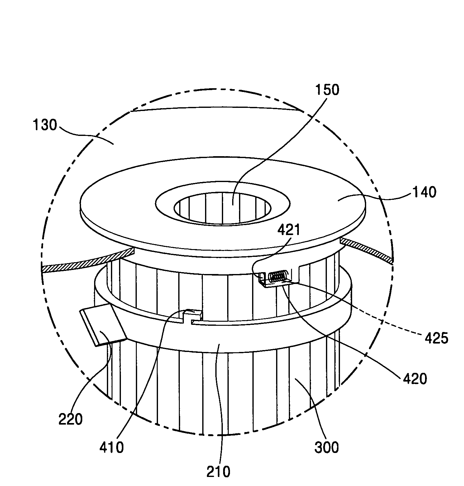
[0073]The filter cleaning unit 200 in accordance with the present invention includes a rotary ring disposed at an outer circumferential surface of the filter 300; a brush supporter 215 connected to the rotary ring 210 and formed in an axial direction of the filter 300 almost as high as a height of the filter300; a blade 220 formed at an outer surface of the brush supporter 215, for rotating the rotary ring by movement of air sucked through the suction opening 120; and a brush 230 mounted inside the brush supporter 215, for removing dust attached to the surface of the filter 300 by being rotat...


PUM

PropertyMeasurementUnit
rotation forceaaaaaaaaaa
lifting forceaaaaaaaaaa
rotationaaaaaaaaaa

Abstract

A filter device for a vacuum cleaner includes a casing having a collecting space therein, a suction opening through which air including dust is sucked, formed eccentrically at one side so that sucked air can be rotated and a discharge opening through which purified air is discharged. A filter is installed at an internal space of the casing, for filtering dust from air sucked through the suction opening. A filter cleaning unit is disposed at an outer circumferential surface of the filter, for cleaning the filter by being rotated by a rotation force of air sucked through the suction opening. A rotation restrainer is provided for restraining rotation of the filter cleaning unit when the filter cleaning unit reaches a topmost position. Accordingly, fine dust attached to the filter in cleaning is removed so that a channel of the filter can be prevented from being closed.

Description

BACKGROUND OF THE INVENTION[0001]1.Field of the Invention[0002]The present invention relates to a vacuum cleaner, and more particularly, to a filter device of a vacuum cleaner capable of self-removing dust attached to a filter in operation of a cleaner.[0003]2.Description of the Background Art[0004]In general, a vacuum cleaner is an electronic device for cleaning an indoor space such as a room, an office or the inside of a car and can remove undesired impurities such as dust existing at home or the inside of a car by using a suction force thereof.[0005]FIG. 1 is a perspective view showing a structure of a general vacuum cleaner.[0006]As shown therein, a general vacuum cleaner includes a cleaner main body 1 and a suction head 3 connected to the cleaner main body 1 by a suction hose 5 and an expansion pipe 4, for sucking dust and foreign substances from a floor.[0007]The cleaner main body 1 includes a suction force generating part (not shown) for generating a suction force; and a filt...

Claims


Application Information

Patent Timeline
Patent Type & Authority Patents(United States)
IPC IPC(8): A47L9/16A47L9/20B01D46/00B01D46/04B01D46/24B01D46/42
CPCA47L9/1666A47L9/20B01D46/0046B01D46/0065B01D46/0075B01D46/2411B01D2279/55Y10S55/03Y10S55/02B01D46/681B01D46/76
Inventor NAM, HYEUN-SIKLEE, YONG-WOOCHUNG, CHOON-MYUNREW, HO-SEON
Owner LG ELECTRONICS INC
Why Eureka
Try Eureka