AI technical title is built by PatSnap AI team. It summarizes the technical point description of the patent document.
a technology of flying lead wire and bonding process, which is applied in the direction of manufacturing tools, instruments, non-electric welding apparatus, etc., can solve the problem that the conventional wire bonding process is not useful in fabricating such structures
Inactive Publication Date: 2009-02-24
GLOBALFOUNDRIES INC
View PDF10 Cites 108 Cited by
Summary
Abstract
Description
Claims
Application Information
AI Technical Summary
This helps you quickly interpret patents by identifying the three key elements:
Problems solved by technology
Method used
Benefits of technology
Benefits of technology
The present invention provides a process for bonding wires to an electronic circuit device with one end attached to the surface of the device and the other end extending away from the surface. The wires can also be formed at an angle or have curved features. This process allows for more efficient and secure wiring of electronic circuits.
Problems solved by technology
If it is desired that the wires bonded to the surface be used as an electronic device probe (as described herein) or to interconnect an array of contact pads on a first surface to another array of contact pads on a second surface which is facing the first surface, the conventional wire bonding process is not useful to fabricate such structures.
Method used
Image
Click on the blue label to locate the original text in one second.
Reading with bidirectional positioning of images and text.
Examples
Embodiment Construction
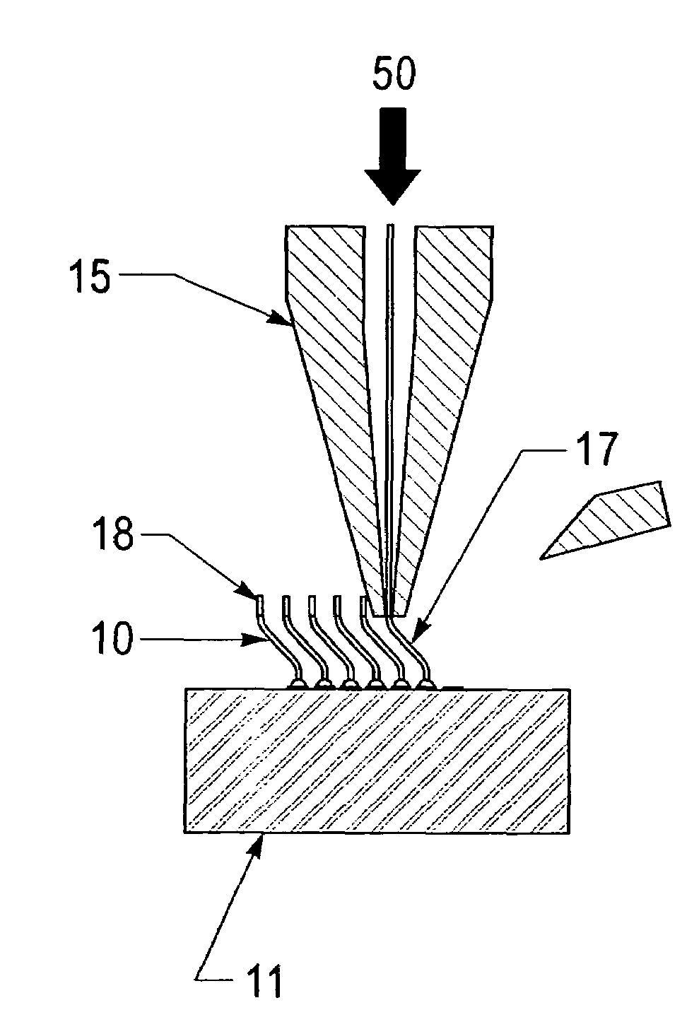
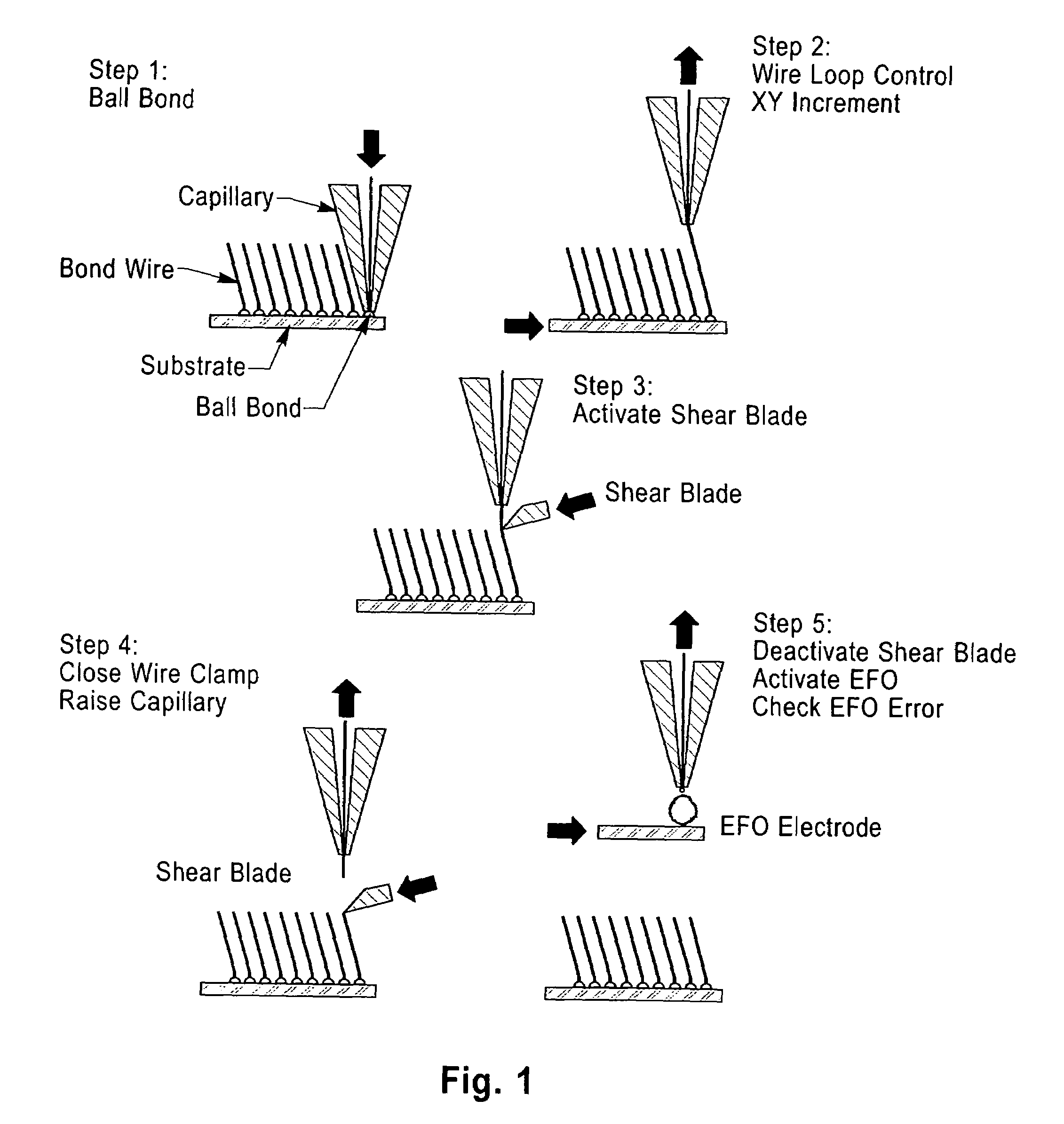
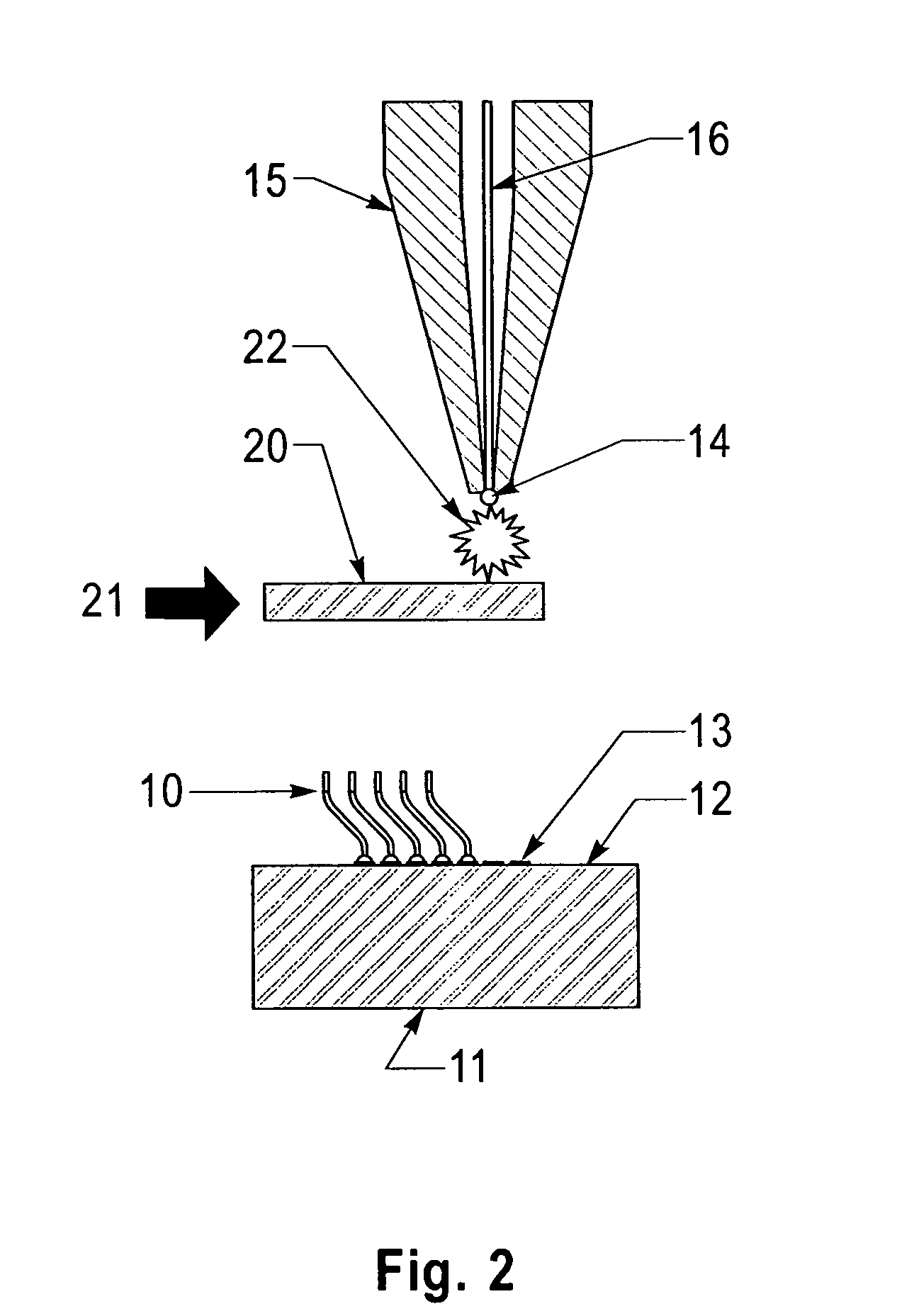
[0019]Structures according to the present invention are made using a wire bonding operation is shown in FIG. 1 and starts by forming a ball on the end of a (preferably) gold wire 110 that is threaded through a hollow pointed ceramic tool called a capillary 115. The ball 112 is pressed against the first bonding surface 116 of substrate 118 while the substrate 118 is heated from below and ultrasonic energy is applied through the capillary 115 as shown in step 1 of FIG. 1. The metallurgy on the surface of the substrate is critical to the wire bonding process. After ball bonding the wire to the first substrate surface 116, the capillary 115 is raised while the substrate is moved (shown by arrow 120) to create a loop shape in the wire (FIG. 1—step 2). The capillary 115 is then lowered to press the side 124 of the wire against the second substrate 126 surface 128 to form the second bond or wedge bond 130 (FIG. 1—step 3). The capillary is raised slightly indicated by arrow 132 and a mechan...
PUM
Property
Measurement
Unit
diameter
aaaaa
aaaaa
diameter
aaaaa
aaaaa
shape
aaaaa
aaaaa
Abstract
A method is described having the steps of providing a surface having a plurality of wire bondable locations, wire bonding a wire to each of the wire bondable locations using a wire capillary tool; controlling the position of the capillary tool with respect to the substrate; after forming a wire bond of the wire to the wire bondable location moving the capillary tool relative to the surface as the capillary tool is moved away from the surface to form a wire having a predetermined shape.
Description
[0001]This application is a DIV of application Ser. No. 10 / 342,167 (filed on Jan. 14, 2003), now U.S. Pat. No. 6,708,403, which is a CON of application Ser. No. 09 / 871,536 (filed on May 31, 2001), now U.S. Pat. No. 6,526,655, which is a DIV of application Ser. No. 09 / 164,470 (filed on Oct. 1, 1998), now U.S. Pat. No. 6,295,729, which claims benefit of application Ser. No. 60 / 060,877 (filed on Oct. 2, 1997) and which is a CIP of application Ser. No. 09 / 088,394 (filed on Jun. 1, 1998) now U.S. Pat. No. 6,300,780, which is a DIV of application Ser. No. 08 / 754,869 (filed on Nov. 22, 1996) now U.S. Pat. No. 5,821,763, which is a CON of application Ser. No. 08 / 055,485 (filed on Apr. 30, 1993) now U.S. Pat. No. 5,635,846, which is a CIP of application Ser. No. 07 / 963,346 (filed on Oct. 19, 1992) now U.S. Pat. No. 5,371,654.FIELD OF THE INVENTION[0002]The present invention is directed to a process for bonding wires to surfaces, for example, to form electronic device probes, or to form elect...
Claims
Application Information
Patent Timeline
Application Date:The date an application was filed.
Publication Date:The date a patent or application was officially published.
First Publication Date:The earliest publication date of a patent with the same application number.
Issue Date:Publication date of the patent grant document.
PCT Entry Date:The Entry date of PCT National Phase.
Estimated Expiry Date:The statutory expiry date of a patent right according to the Patent Law, and it is the longest term of protection that the patent right can achieve without the termination of the patent right due to other reasons(Term extension factor has been taken into account ).
Invalid Date:Actual expiry date is based on effective date or publication date of legal transaction data of invalid patent.

