Multipurpose radio

a multi-purpose, radio technology, applied in the field of radio, can solve the problems of not being usable for illumination or other purposes, and the conventional radio is simply used for broadcasting

Inactive Publication Date: 2009-02-24
YEN JEN YEN
View PDF2 Cites 7 Cited by
  • Summary
  • Abstract
  • Description
  • Claims
  • Application Information

AI Technical Summary

Problems solved by technology

Further, conventional radios are simply used for broadcasting, not usable for illumination or other purposes

Method used


Image

  • Multipurpose radio
  • Multipurpose radio
  • Multipurpose radio

Examples


Embodiment Construction

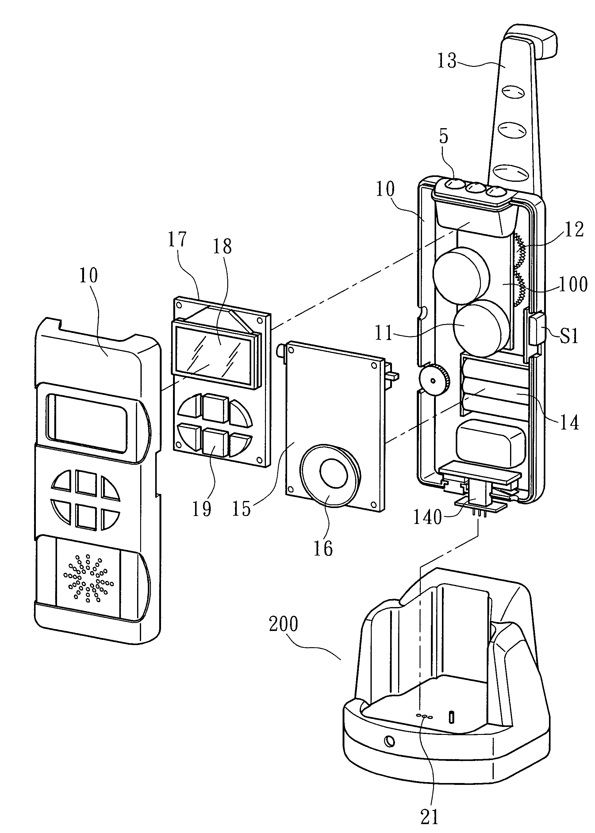
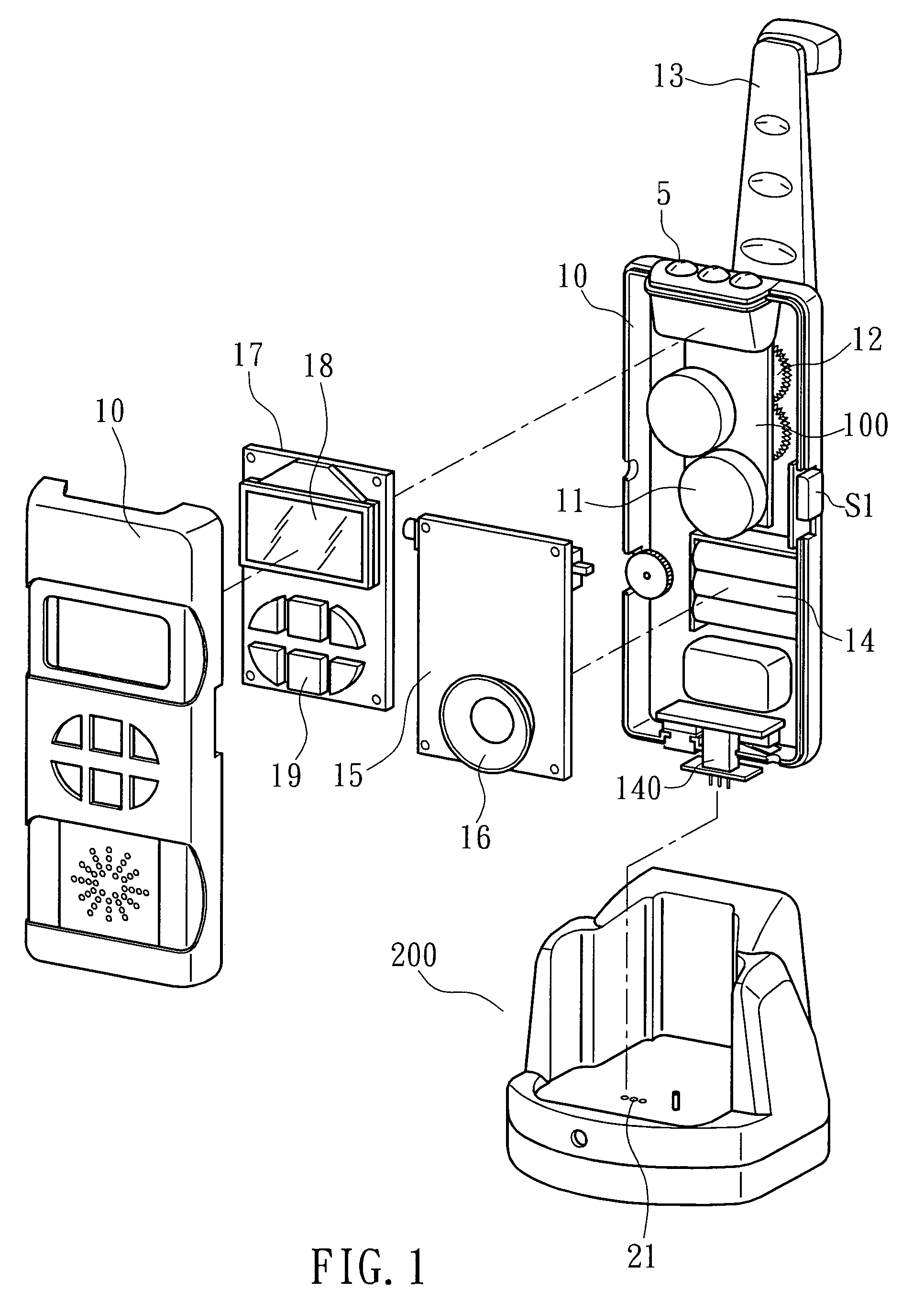
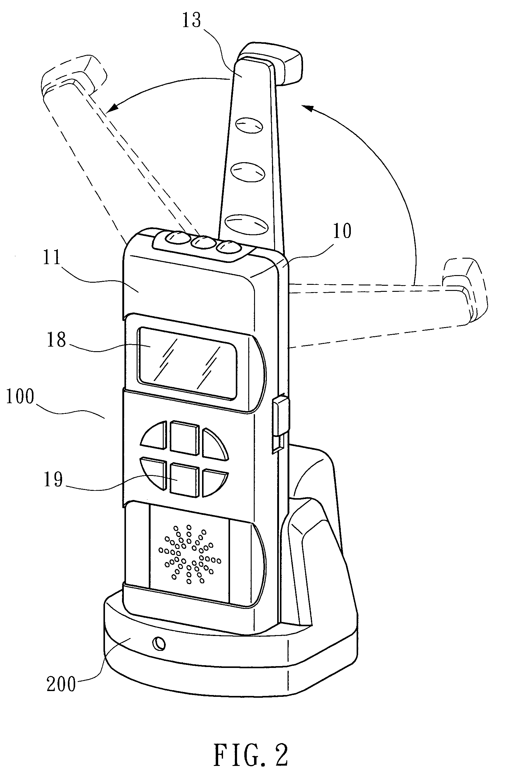
[0010]Referring to FIGS. 1˜4, a radio in accordance with the present invention is shown comprising a housing 10. The housing 10 houses a power control unit 100, a radio circuit unit 15, and a function mode display unit 17.

[0011]The power control unit 100 comprises a dynamo 11, a rectifier 1, a hand-driven charging circuit 2, a city power supply charging circuit 3, a power failure auto-lighting circuit 4, and a LED lamp 5. A crank handle 13 is coupled to the dynamo 11 through a transmission gear set 12. The rectifier 1 is comprised of diodes D11˜D16 and adapted to rectify AC into DC. The hand-driven charging circuit 2 is comprised of a transistor Q16 and a zener diode ZD2. The hand-driven charging circuit 2 is off when the dynamo 11 is off. When the dynamo 11 is working, the hand-driven charging circuit 2 is driven to charge the battery 14 with the output DC power supply o the dynamo 11. The city power supply charging circuit 3 is comprised of a transistor Q11 and an electric plug 14...


PUM


Abstract

A multipurpose radio is disclosed to include a power control unit, which uses a rechargeable battery to provide the necessary working voltage to a LED lamp for illumination, a hand-driven dynamo to generate electricity for recharging the rechargeable battery, a power adapter for charging the rechargeable battery with city power supply, a radio circuit unit for receiving AM and FM radio broadcasting signals, TV audio signals and NOAA signals, and a function mode display unit, which uses a speaker for voice output, a screen for data display, and a selector key for frequency selection.

Description

BACKGROUND OF THE INVENTION[0001]1. Field of the Invention[0002]The present invention relates to a radio and more particularly, to such a multipurpose radio having a hand-driven power generator means.[0003]2. Description of the Related Art[0004]Conventional mobile radios commonly use a battery to provide the necessary working voltage. When the power of the battery of a radio is low, the battery must be immediately replaced. In case no new battery is available, the radio becomes not operable. Therefore, a person must carry a certain number of battery cells when using a radio in a high mountain. Further, conventional radios are simply used for broadcasting, not usable for illumination or other purposesSUMMARY OF THE INVENTION[0005]The present invention has been accomplished under the circumstances in view. According to one aspect of the present invention, the multipurpose radio is equipped with a LED lamp and a rechargeable battery for illumination. According to another aspect of the ...

Claims


Application Information

Patent Timeline
Patent Type & Authority Patents(United States)
IPC IPC(8): G08B5/22H02J7/00H04B1/38
CPCH02J7/32H02K7/1861H04B1/1607
Inventor YEN, JEN-YEN
Owner YEN JEN YEN
Why Eureka
Try Eureka