Traffic light status remote sensor system

a technology of remote sensor and traffic light, which is applied in the direction of traffic control supervision, instruments, transportation and packaging, etc., can solve the problems of inability to afford to install photo-enforcement systems, municipalities may lose money, etc., and achieve the effect of improving the efficiency of documenting red light violators, reducing installation costs, and increasing intersection safety

Inactive Publication Date: 2009-02-24
OPTOTRAFFIC
View PDF27 Cites 43 Cited by
  • Summary
  • Abstract
  • Description
  • Claims
  • Application Information

AI Technical Summary

Benefits of technology

[0005]The disclosed system eliminates the installation costs associated with interfacing the traffic signal controller with Red Light Camera applications. In conjunction with non-intrusive speed estimation technologies (such as laser or video speed sensors), the remote sensor system makes possible the development of a fully transportable photo-enforcement system. This is a significant development for smaller municipalities and police departments who cannot afford to install photo-enforcement systems in many intersections.
[0006]Implementing a removable photo-enforcement system helps improve the efficiency of documenting red light violators. Another advantage of the disclosed remote system working in combination with a red-light photo-enforcement system is that the decision making process is based on exactly what a driver sees upon entering an intersection. If, for any reason, a traffic light is broken or hidden, and the driver cannot determine the state of the traffic light, neither will the sensor. In addition, immediate information about a light malfunction may be communicated to a control office, enabling immediate action to fix the light and / or dispatch personnel, thus increasing the safety of the intersection.

Problems solved by technology

This is a significant development for smaller municipalities and police departments who cannot afford to install photo-enforcement systems in many intersections.
If, for any reason, a traffic light is broken or hidden, and the driver cannot determine the state of the traffic light, neither will the sensor.
In other words, when drivers realize that an intersection has been instrumented they tend to stop violating and the municipalities may lose money.

Method used


Image

  • Traffic light status remote sensor system
  • Traffic light status remote sensor system
  • Traffic light status remote sensor system

Examples


Embodiment Construction

[0017]The invention summarized above and defined by the enumerated claims may be better understood by referring to the following description, which should be read in conjunction with the accompanying drawings. This description of an embodiment, set out below to enable one to build and use an implementation of the invention, is not intended to limit the invention, but to serve as a particular example thereof. Those skilled in the art should appreciate that they may readily use the conception and specific embodiments disclosed as a basis for modifying or designing other methods and systems for carrying out the same purposes of the present invention. Those skilled in the art should also realize that such equivalent assemblies do not depart from the spirit and scope of the invention in its broadest form.

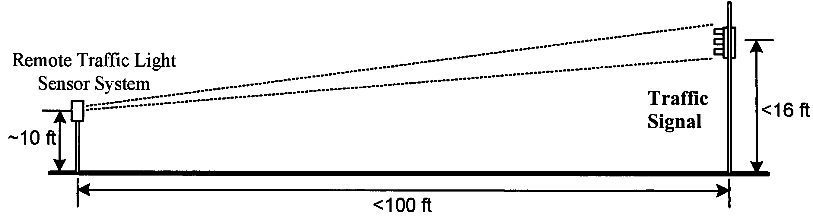
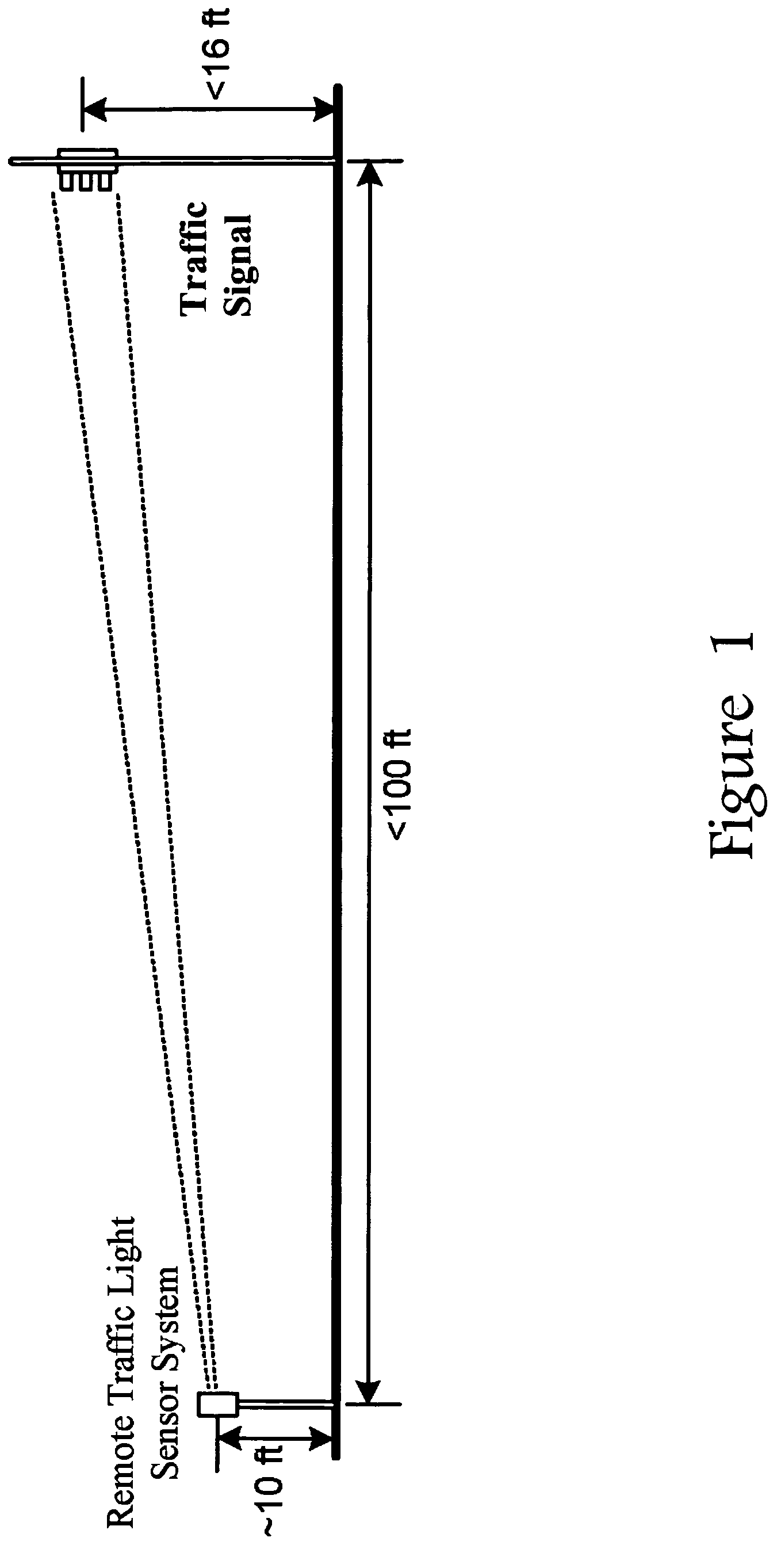
[0018]Referring now to the figures, the basic principle of operation of the disclosed sensor system is illustrated in FIG. 1, which shows the geometrical design of a remote traffic light...


PUM


Abstract

A Traffic-Light Status Remote Sensor System is disclosed. The basic system consists of a set of lenses, detectors, and narrowband filters. The sensor system is capable of determining the status of a traffic light (red, amber, or green) from a distance, without any connection to the electronic boards controlling the traffic light. A portable red-light photo-enforcement system working independently from the traffic light controllers is a potential application of the remote traffic light sensor.

Description

BACKGROUND OF THE INVENTION[0001]1. Field of the Invention[0002]This invention relates to a system and method for automatically determining the status of a traffic control signal and more particularly the invention relates to a system for monitoring and recording the status of a traffic signal by observing the light emitted from one or more traffic lights and using the resultant information as input to a traffic monitoring system in a controlled intersection.[0003]2. Background of the Invention[0004]Installing a red light photo-enforcement system in an intersection involves digging the road and pavement in order to install cables for interfacing the violation detecting / recording system with the traffic light controller for synchronization. This requirement makes the red light photo-enforcement system a permanent installation for a specific approach at an intersection. The disclosed invention eliminates the need for a cable connection between a light controller and a photo-enforcemen...

Claims


Application Information

Patent Timeline
Patent Type & Authority Patents(United States)
IPC IPC(8): G08G1/095
CPCG08G1/095G08G1/097G08G1/0175
Inventor SIROTA, J. MARCOSSEAS, ANTONIOSMOSTOFI, DAVID
Owner OPTOTRAFFIC
Why Eureka
Try Eureka