Damage and wear detection for rotary cutting blades

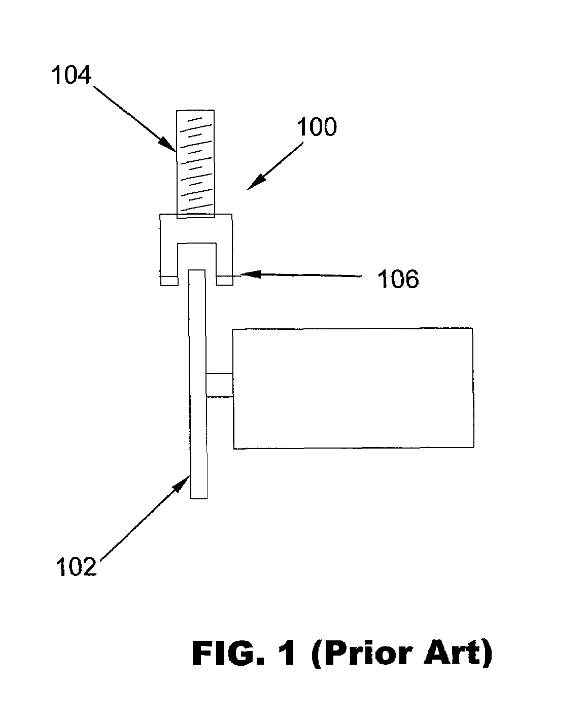
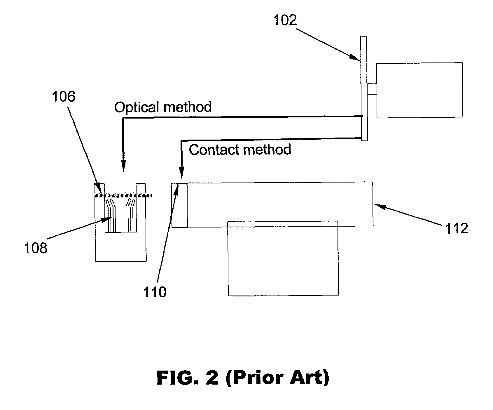
a rotary cutting blade and wear detection technology, which is applied in the field of single-chip systems, can solve the problems of reducing the diameter of the blade, slow contact and optical methods of measuring the extent of wear of the blade as described above, and inhibiting normal machine operation, so as to reduce the travel time of the sensor and detect blade damage and wear more efficiently

Active Publication Date: 2009-02-24
ASM ASSEMBLY AUTOMATION LTD
View PDF3 Cites 41 Cited by
  • Summary
  • Abstract
  • Description
  • Claims
  • Application Information

AI Technical Summary

Benefits of technology

[0012]It is thus an object of the invention to seek to provide a blade detection system which detects blade damage and wear more efficiently than the aforesaid prior art and which reduces travel time for a sensor while performing damage detection and wear detection.

Problems solved by technology

Additionally, the blade will wear out after a period of sawing, resulting in the blade having a reduced diameter.
Both the contact and optical methods of measuring the extent of wear of the saw blade as described above are slow and inhibit normal machine operation as the saw blade 102 during the singulation operation is far from the optical sensor or the reference surface.
This makes the machine complex and increases the number of components required.
The toggling between the two detection functions at the two locations is undesirable as this affects the reliability and stability of measuring the blade wear value.

Method used


Image

  • Damage and wear detection for rotary cutting blades
  • Damage and wear detection for rotary cutting blades
  • Damage and wear detection for rotary cutting blades

Examples


Embodiment Construction

[0025]The preferred embodiment of the present invention will be described hereinafter with reference to the accompanying drawings.

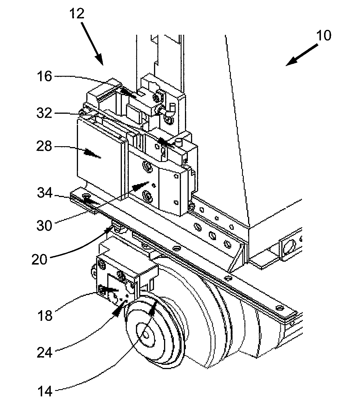
[0026]FIG. 3 is an isometric view of a singulation system 10 for singulating substrates incorporating a blade detection system 12 according to the preferred embodiment of the invention. The blade detection system 12 is located immediately above a rotary saw blade 14. This system 12 further comprises a home sensor 16, a sensor housed in a sensor housing 18, cylindrical guide rods 20, movable coils and other connecting parts. A through beam sensor is located within the sensor head 24 and enclosed in the sensor housing 18.

[0027]The sensor housing 18 may be driven by a linear direct drive motor mechanism comprising a linear motor 28 and a movable assembly 30 and indexed up and down using the guide rods 20 and a bearing 26. The sensor housing 18 is connected to the direct drive motor mechanism via the cylindrical guide rods 20 so as to drive the sensor housing...


PUM

PropertyMeasurementUnit
diameteraaaaaaaaaa
distanceaaaaaaaaaa
speedaaaaaaaaaa

Abstract

A method of detecting wear and damage to a rotary cutting blade for singulating a substrate is provided comprising the steps of providing a sensor to locate a first detecting position at an edge of the blade and performing dicing with the blade while the sensor is maintained substantially at the first detecting position for detecting damage to the blade. Subsequently, an extent of wear of the blade is determined by driving the sensor in the direction of the blade to locate a second detecting position at the edge of the blade as a diameter of the blade is reduced due to dicing. Thereafter, while dicing is performed with the blade, the sensor is maintained substantially at the second detecting position for detecting damage to the blade.

Description

FIELD OF THE INVENTION[0001]The present invention relates to a singulation system for cutting and separating electronic components, and in particular, to a singulation system comprising a rotary cutting blade.BACKGROUND AND PRIOR ART[0002]A singulation system for singulation or dicing electronic components, such as semiconductor substrates or packaged semiconductor devices, comprises at least a spindle system and a carrier support such as a chuck table. The axis of the spindle system is orthogonal to the axis of the chuck table and a theta axis table is located on top of the chuck table. The spindle system typically includes either one or two high speed rotary shafts with a cutting blade comprising a circular saw blade each.[0003]Dicing may be performed on the semiconductor substrate in one direction by moving the chuck table under a spindle axis while the saw blade is cutting the semiconductor substrate on a carrier, such as a saw jig, on the theta axis table of the chuck table. Th...

Claims


Application Information

Patent Timeline
Patent Type & Authority Patents(United States)
IPC IPC(8): G01N21/00B24B49/00
CPCB23D59/001B24B27/06B24B49/12G01N2021/151
Inventor CHENG, CHI WAHCHOW, LAP KEI ERIC
Owner ASM ASSEMBLY AUTOMATION LTD
Why Eureka
Try Eureka