Multi-pass parallel-tube heat exchanger

a heat exchanger and parallel tube technology, applied in the direction of fluid pressure control, instruments, immersion heating arrangements, etc., can solve the problems of heat exchanger tubing being clogged, time-consuming and messy, and shell and tube heat exchangers suffer from several drawbacks and limitations, so as to facilitate manufacturing, easy to alter or reconfigure, and easy to clean

Active Publication Date: 2009-02-24
VERTIV CORP
View PDF14 Cites 12 Cited by
  • Summary
  • Abstract
  • Description
  • Claims
  • Application Information

AI Technical Summary

Benefits of technology

[0012]The heat exchanger may also be effectively operated in any position or orientation. Furthermore, the present invention can be made from any desired material including standard piping. As such, the heat exchanger may be manufactured so it is not an ASME vessel and, thus, does not require a pressure-relief valve. This design also makes the present invention lighter, cheaper, easier to manufacture, easier to clean and easier to alter or reconfigure.

Problems solved by technology

However, shell and tube type heat exchangers suffer from several drawbacks and limitations.
In certain condenser applications, heat exchanger tubing can become clogged if the supply fluid is not cleaned.
Unlike plate-to-plate and co-axial heat exchangers, shell and tube heat exchangers can be cleaned, but this is often difficult, time consuming and messy.
This takes time and often requires special tools.
This operation again can be time consuming and improper positioning of the new gasket, improper coupling of the head to the shell, or failure to use a new gasket can render the exchanger inoperable.
In addition, shell and tube heat exchangers are often limited in terms of the flow patterns they can provide for the shell-side fluid relative to the tube-side fluid.
The availability of only cross-flow in conventional shell and tube heat exchangers is often limiting on the performance that can be obtained from such devices.
Conventional shell and tube exchangers are often restricted to specific flow circuit arrangements or are costly to modify.
A still further limitation of conventional shell and tube exchangers is their size.
Moreover, because of the design of shell-and-tube exchangers, the design of the unit is often restricted to a particular configuration and shape and is further restricted to a unit that must be positioned in a horizontal orientation.
The large size and configuration requirements of such shell-and-tube exchangers not only causes problems in terms of space and positioning requirements but it also often requires that the shell, in essence a large pressure vessel, include a pressure relief valve and meet various other standards, for example pressure vessel codes promulgated by the American Society of Mechanical Engineers (ASME), that apply to large pressure vessels.
The size drawback resultant from shell-and-tube exchangers is becoming even more problematic as regulations controlling the use of various refrigerants are implemented.
In general, non-azeotropic refrigerants are less effective than azeotropic refrigerants.
Such a size increase further exacerbates the size difficulties posed by shell-and-tube exchangers.
The size limitations posed by shell-and-tube exchangers is still further exacerbated when such exchangers are used as condensers or when sub-cooling or de-superheating is required.
The limitations and disadvantages of shell-and-tube exchangers are especially acute in certain applications, such as applications associated with cooling systems for electronic equipment.
Moreover, because such rooms are typically established in existing buildings, there are often space and sizing requirements.

Method used


Image

  • Multi-pass parallel-tube heat exchanger
  • Multi-pass parallel-tube heat exchanger
  • Multi-pass parallel-tube heat exchanger

Examples


Embodiment Construction

[0021]Illustrative embodiments of the invention are described below. In the interest of clarity, not all features of an actual implementation are described in this specification. It will of course be appreciated that in the development of any such actual embodiment, numerous implementation-specific decisions must be made to achieve the developers' specific goals, such as compliance with system-related and business-related constraints, which will vary from one implementation to another. Moreover, it will be appreciated that such a development effort might be complex and time-consuming, but would nevertheless be a routine undertaking for those of ordinary skill in the art having the benefit of this disclosure.

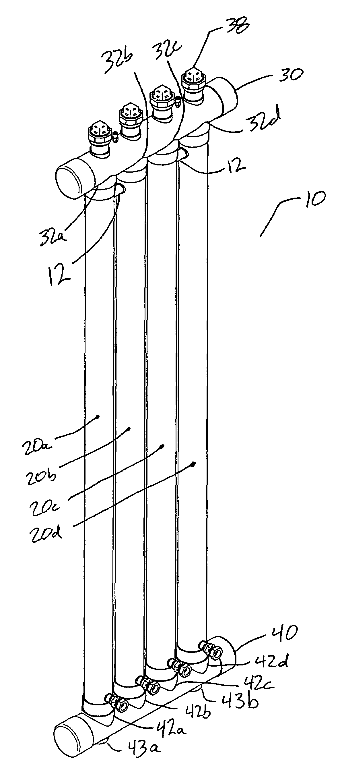
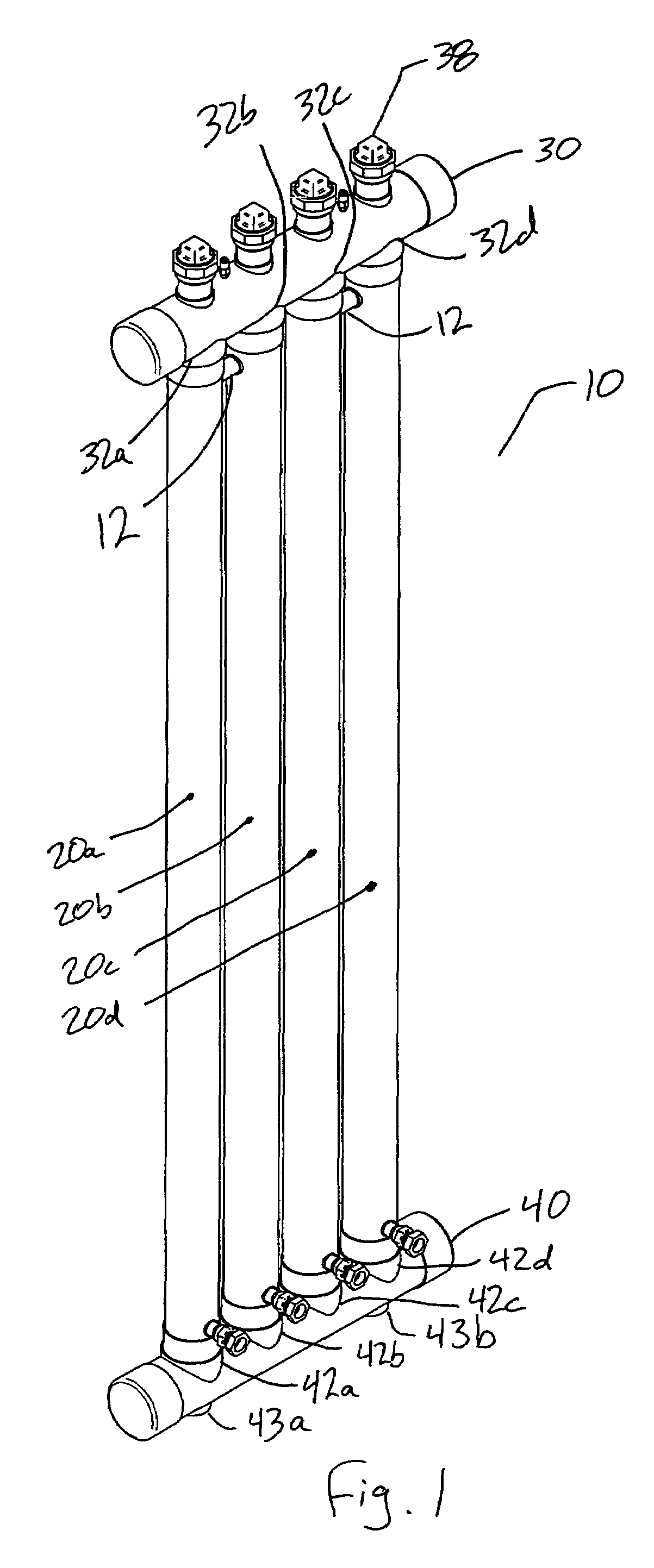
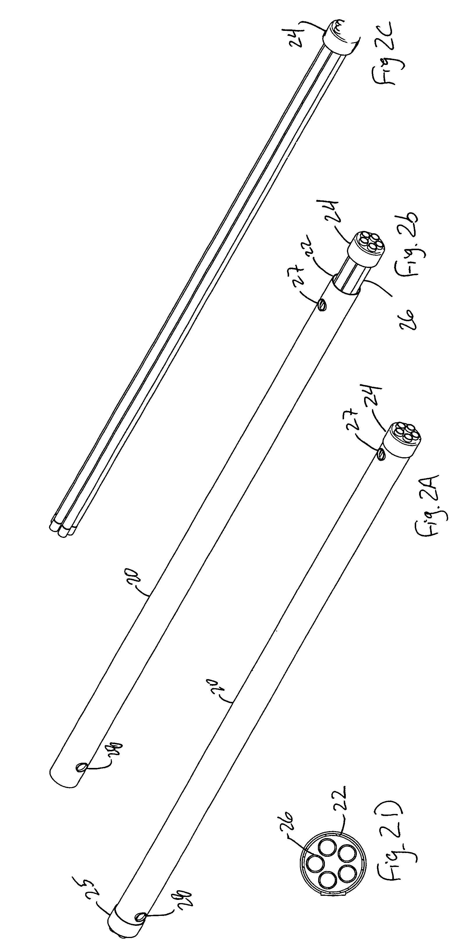
[0022]Turning to the drawings, particularly FIG. 1, a multi-pass parallel-tube heat exchanger 10 constructed in accordance with certain teachings of this disclosure is illustrated. Heat exchanger 10 is formed from a number of shell-tubes 20. Each shell-tube includes an outer shel...


PUM


Abstract

A multi-pass parallel tube heat exchanger is disclosed. The multi-pass parallel tubes heat exchanger provides a compact, light and inexpensive heat exchanger that may be oriented in any direction. These features and others make the disclosed exchanger ideal for use in a restricted area such as that available when providing localized cooling systems. This design is more efficient than the prior art and allows for a versatile operation with multiple circuiting options for the flow path and enhanced performance with multiple fluid and heat transfer operations.

Description

CROSS-REFERENCE TO RELATED APPLICATIONS[0001]This application claims the benefit of U.S. provisional application No. 60 / 488,249 filed Jul. 18, 2003, the entire disclosure of which is incorporated herein by reference.BACKGROUND OF THE INVENTION[0002]Refrigeration systems often use various types of heat exchangers, such as plate-to-plate, co-axial or shell and tube, as an evaporator or a condenser. In many applications, shell and tube heat exchangers are employed as condensers. However, shell and tube type heat exchangers suffer from several drawbacks and limitations.[0003]In certain condenser applications, heat exchanger tubing can become clogged if the supply fluid is not cleaned. Unlike plate-to-plate and co-axial heat exchangers, shell and tube heat exchangers can be cleaned, but this is often difficult, time consuming and messy. Generally, the cleaning of a shell and tube exchanger requires removal of the shell-and-tube heads and the gasket positioned between the heads and the sh...

Claims


Application Information

Patent Timeline
Patent Type & Authority Patents(United States)
IPC IPC(8): F24H1/10F28D7/16F28F9/26
CPCF28D7/16F28F9/26F28G13/00
Inventor MOLAVI, ANTHONY S.
Owner VERTIV CORP
Why Eureka
Try Eureka