
Mist spraying apparatus and image forming apparatus

a spraying apparatus and spraying technology, applied in the direction of printing, inking apparatus, etc., can solve the problems of unstable meniscus at the nozzle connected to the ink chamber, difficult to achieve a high viscosity spray of ink, and inability to break down the meniscus, etc., to achieve high viscosity, high viscosity, and high quality image

Inactive Publication Date: 2009-03-03
FUJIFILM CORP
View PDF2 Cites 0 Cited by
  • Summary
  • Abstract
  • Description
  • Claims
  • Application Information

AI Technical Summary

Benefits of technology

The present invention is about a mist spraying apparatus and an image forming apparatus that can spray high-viscosity liquids in the form of a mist. The apparatus includes a liquid chamber, a coil, a diaphragm, a spraying port, and a drive unit. The diaphragm vibrates ultrasonically due to a magnetic force generated by the coil, and the liquid is converted into a mist and sprayed from the spraying port. The apparatus can spray even high-viscosity liquids and form high-quality images.

Problems solved by technology

By utilizing the displacement (distortion) generated in the thickness direction of the piezoelectric body, when a diaphragm is caused to vibrate and an ultrasonic wave is applied to the ink inside an ink chamber, the meniscus at the nozzle connected to the ink chamber becomes unstable, and ink in the form of a mist is sprayed from the nozzle.
However, in an ink mist type image forming apparatus using a conventional piezoelectric body, it is difficult to achieve a mist spray of ink having a high viscosity (for example, approximately 20 cP).
However, even if the amplitude is increased in this way, in a conventional image forming apparatus which uses piezoelectric bodies made of PZT, or the like, it is not possible to break down the meniscus of ink having a viscosity of around 20 cP, and therefore, ink of this viscosity cannot be sprayed in the form of a mist.
For example, with a single-plate piezoelectric body, it is not possible to achieve meniscus break-down in ink having a viscosity of 10 cP.

Method used


Image

  • Mist spraying apparatus and image forming apparatus
  • Mist spraying apparatus and image forming apparatus
  • Mist spraying apparatus and image forming apparatus

Examples


Embodiment Construction

Basic Composition of Mist Spraying Apparatus

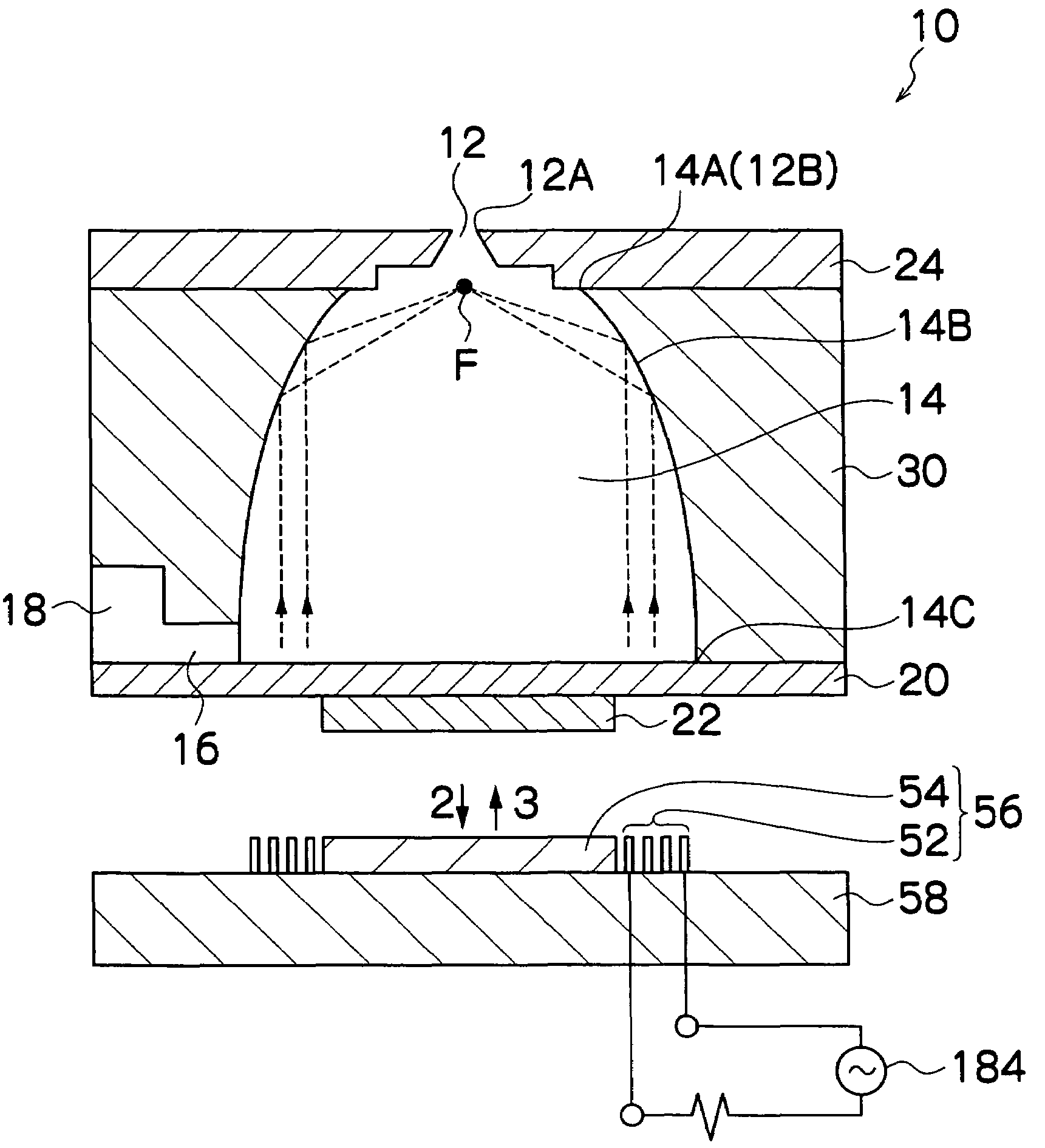
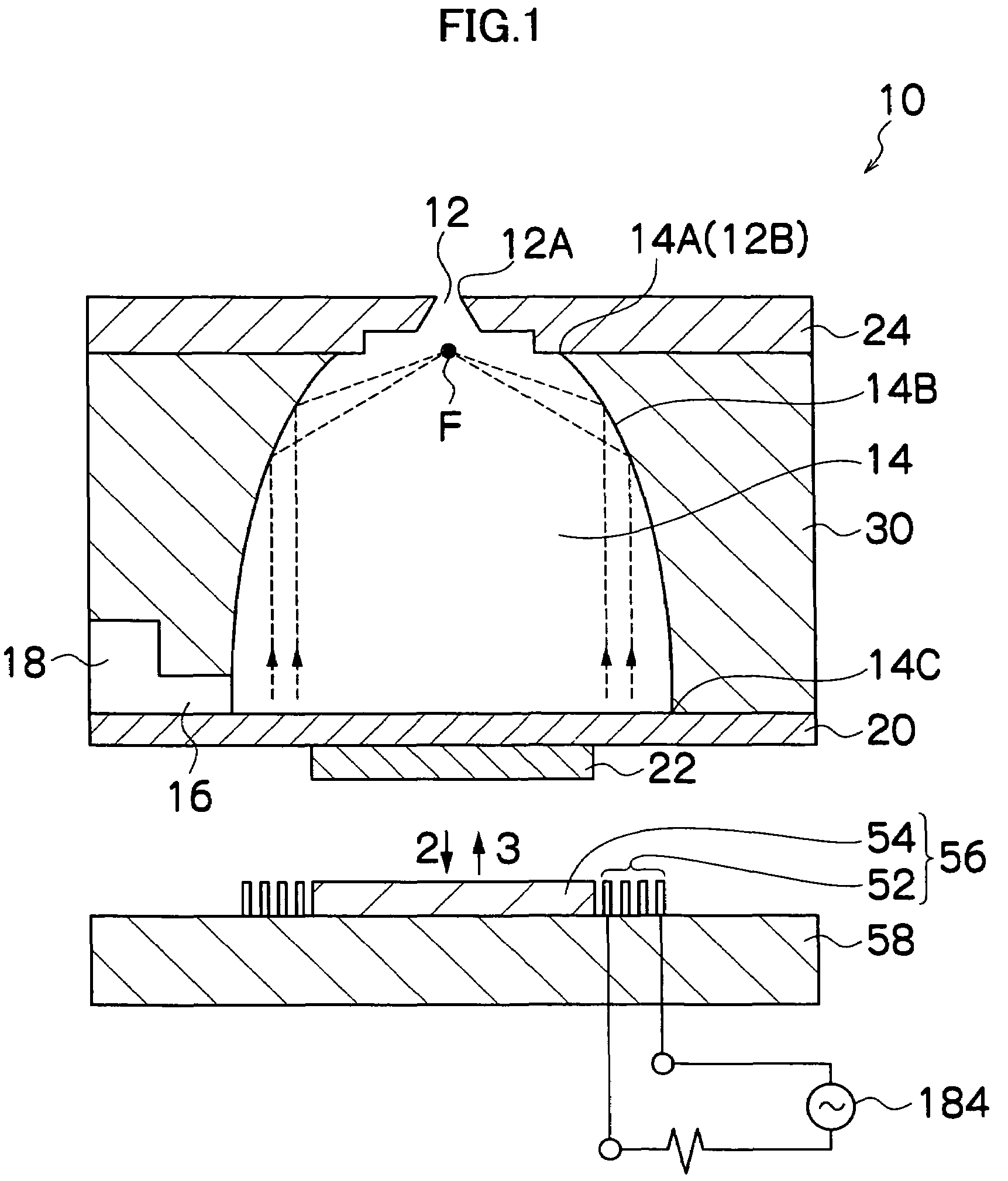
[0039]FIG. 1 is a cross-sectional diagram showing the basic composition of a mist spraying apparatus according to an embodiment of the present invention.

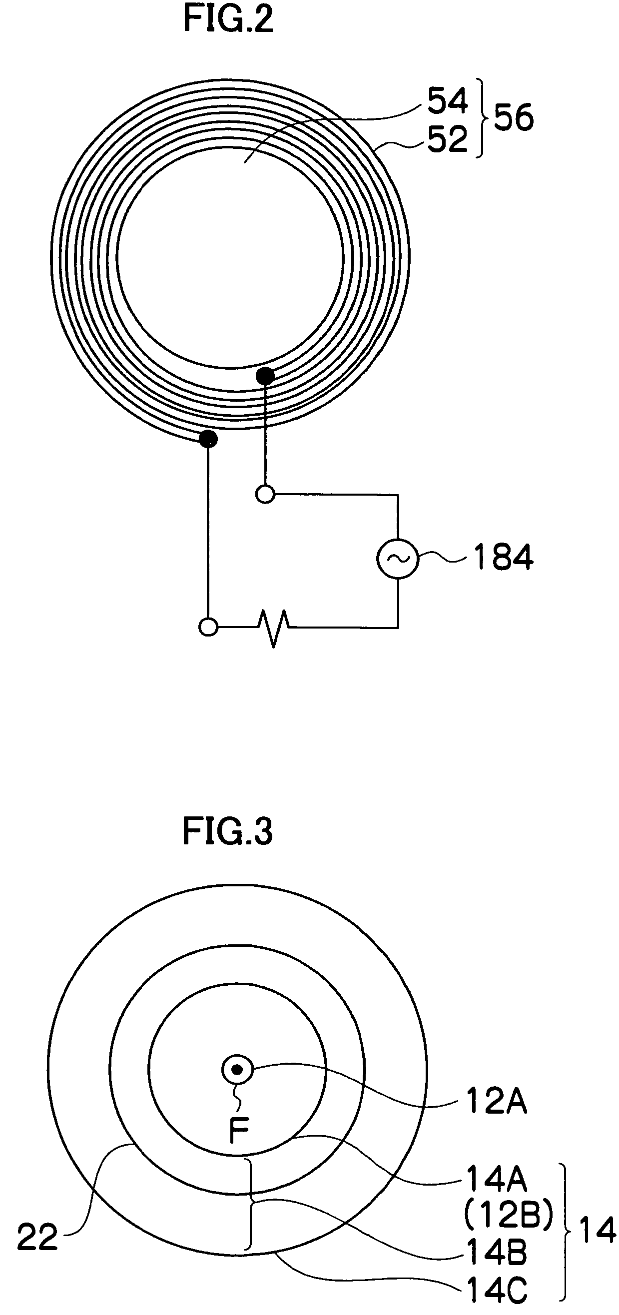
[0040]The mist spraying apparatus 10 shown in FIG. 1 comprises: a nozzle 12 forming an opening from which ink is sprayed; an ink chamber 14 connected to the nozzle 12; an ink supply port 16 forming an opening through which ink is supplied to the ink chamber 14; a common flow channel 18 through which ink to be supplied to the ink chamber 14 through the ink supply port 16 flows; a diaphragm 20 disposed on the opposite side of the ink chamber 14 from the side where the nozzle 12 is located; a magnetic body 22 bonded to the surface of the diaphragm 20 reverse to the surface thereof adjacent to the ink chamber 14; an electromagnet 56 comprising a coil 52 and a core 54, disposed in a position separated from the magnetic body 22 on the diaphragm 20; and a substrate 58 which holds the electromagne...


PUM


Abstract

The mist spraying apparatus comprises: a liquid chamber into which liquid is filled; a coil which is applied with an electrical signal to generate a magnetic filed, the electrical signal having a frequency corresponding to an ultrasonic wave; a diaphragm which is vibrated by the magnetic field generated by the coil, and imparts the ultrasonic wave to the liquid in the liquid chamber; a spraying port which is connected to the liquid chamber and sprays the liquid converted into a mist by the ultrasonic wave; and a drive unit which applies the electrical signal to the coil.

Description

BACKGROUND OF THE INVENTION[0001]1. Field of the Invention[0002]The present invention relates to a mist spraying apparatus and image forming apparatus, and more particularly, to a mist spraying apparatus which sprays a liquid in the form of a mist, and an image forming apparatus which forms images on a recording medium, such as a paper, by means of a mist spray.[0003]2. Description of the Related Art[0004]An ink mist type of image forming apparatus which forms images by generating an ink mist (very fine ink particles) by means of ultrasonic vibration, and depositing this ink mist onto a recording medium, such as paper (see, for example, Japanese Patent Application Publication No. 5-57891 (and in particular, FIG. 3) and “Study on Ink Ejection of Print Head Using Focused Ultrasonic Wave and Nozzle” (Shumpei Kameyama, Hiroshi Fukumoto, and Shusou Wadaka, Journal of the Acoustical Society of Japan, Vol. 60, No. 2, (2004), pp. 53-60)).[0005]Generally, a piezoelectric body is used as a de...

Claims


Application Information

Patent Timeline
Patent Type & Authority Patents(United States)
IPC IPC(8): B41J2/06
CPCB41J2/14B41J2002/041B41J2002/14419B41J2002/14459B41J2202/20B41J2202/21
Inventor ONOZAWA, SHO
Owner FUJIFILM CORP
Learn More