Whole house fan system and methods of installation

a whole house fan and fan technology, applied in ventilation systems, lighting and heating apparatus, heating types, etc., can solve the problems of undesirable noise and fan noise, and achieve the effect of reducing the noise of the fan

Active Publication Date: 2009-03-03
QC MFG
View PDF35 Cites 51 Cited by
  • Summary
  • Abstract
  • Description
  • Claims
  • Application Information

AI Technical Summary

Problems solved by technology

In operation, these fans tend to generate quite a bit of noise because of their large size.
Moreover, vibrations due to the fan being mounted directly on a portion of the building structure can also generate undesirable noise.

Method used


Image

  • Whole house fan system and methods of installation
  • Whole house fan system and methods of installation
  • Whole house fan system and methods of installation

Examples


Embodiment Construction

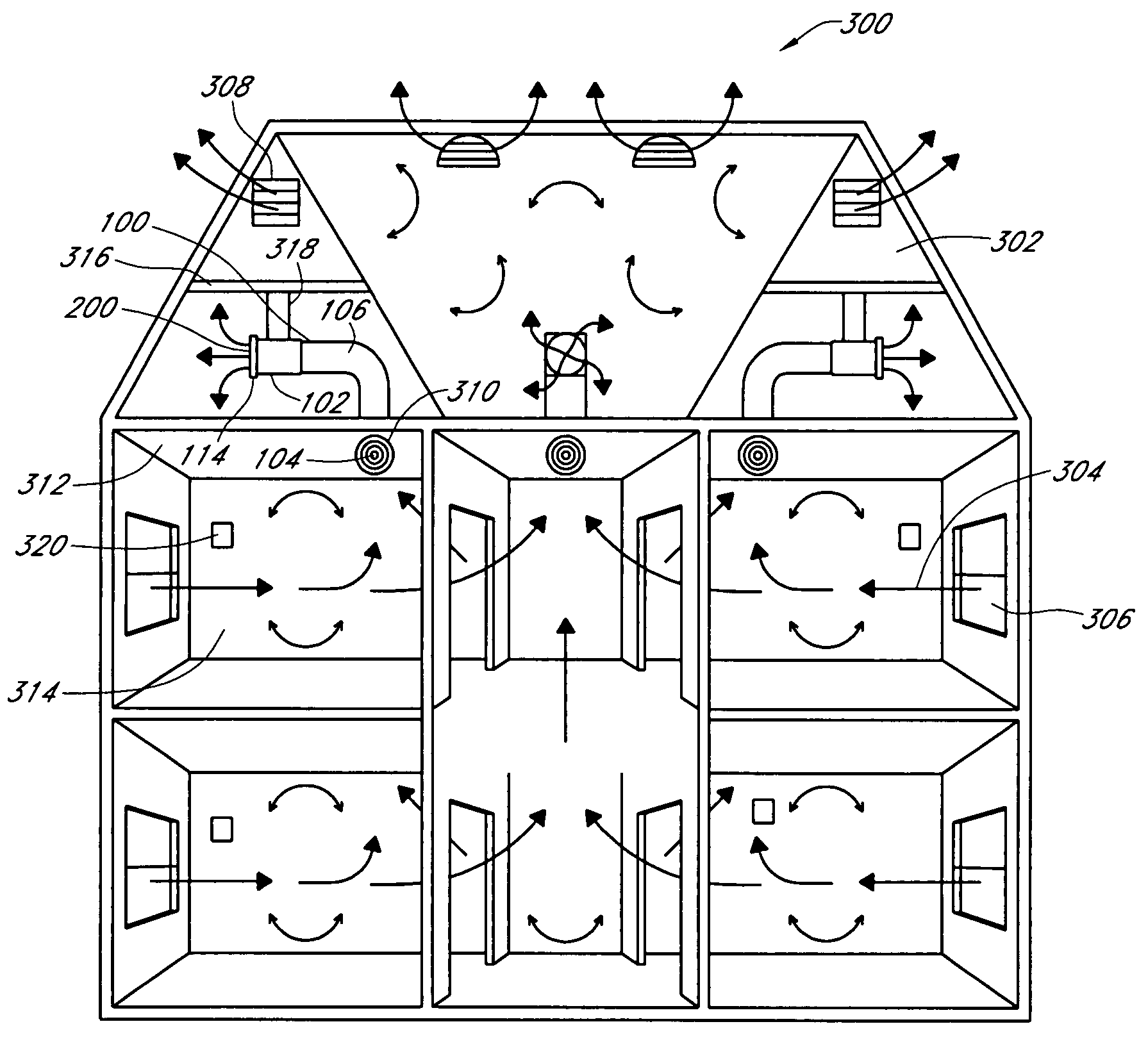
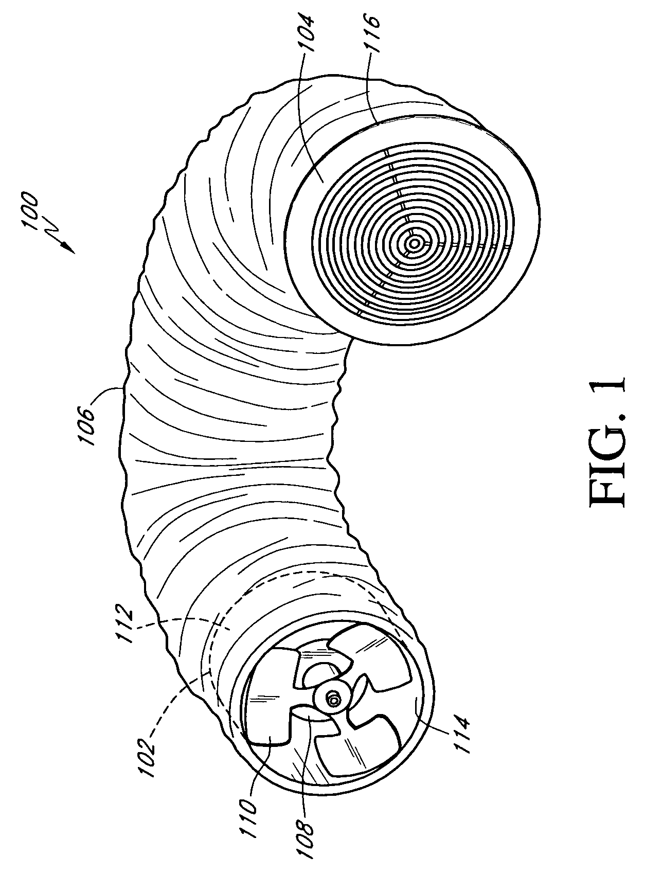
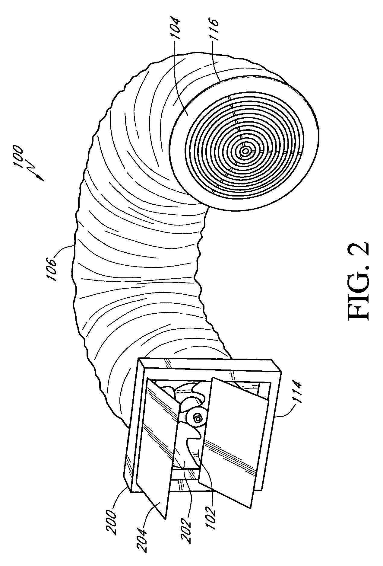
[0012]FIG. 1 is a schematic illustration of a whole house fan system 100 of one preferred embodiment of the present invention. As shown in FIG. 1, the system 100 generally comprises a fan 102, a register or diffuser 104, and a flexible duct 106 extending therebetween. In one embodiment, the fan 102 is comprised of an electric motor 108 and a fan blade system 110 surrounded by a reducing venturi collar 112. In a preferred embodiment, the fan 102 can be a propeller fan, a radial mounted duct fan, or any other similar types of fan. The register or diffuser 104 can also be a grille or any other device that admits air into a space for ventilation purposes. The duct 106 is preferably a flexible, acoustically insulating duct designed to reduce transmission sound therethrough.

[0013]As shown in FIG. 1, the fan 102 and the register 104 are spaced apart by the acoustically insulating duct 106, which reduces transmission of the sound generated by the fan through the register. In the embodiment ...


PUM


Abstract

A whole house fan system and installation methods configured to reduce noise generated by the fan are provided. The system generally includes a fan, a register, and a flexible duct extending between the fan and the register. The flexible duct has acoustical insulation properties, which helps to reduce sound transmission from the fan to the register. The fan system is configured to be mounted in the attic space of a house. The fan motor is suspended in the attic so that it does not have direct contact with any part of the building structure.

Description

RELATED APPLICATIONS[0001]This application claims the benefit of U.S. Provisional Patent Application Ser. No. 60 / 587,537 filed Jul. 13, 2004, the entirety of which is hereby incorporated by reference.BACKGROUND OF THE INVENTION[0002]1. Field of the Invention[0003]This invention relates generally to cooling and ventilation systems for building structures, and more particularly, relates to a low noise whole house fan system and methods of installation.[0004]2. Description of the Related Art[0005]Fans, air conditioners, and various other systems have been developed for cooling and ventilating residential and commercial building structures. Most fan systems are designed to create airflow inside a building. One such type of fan system is a whole house fan system. Whole house fan systems generally operate by drawing cooler air from outside through open windows and doors into the living area of a house. The fan is typically mounted adjacent to an opening formed in the ceiling and draws coo...

Claims


Application Information

Patent Timeline
Patent Type & Authority Patents(United States)
IPC IPC(8): F24F7/06F24F7/007F24F7/013
CPCF24F7/065F24F13/0218F24F2013/242Y10S454/906Y10S454/903
Inventor STEVENSON, DANA CHARLESSTONE, RONNIE KEITH
Owner QC MFG
Why Eureka
Try Eureka