
Linear capacitance measurement and touchless switch

a capacitance measurement and touchless switch technology, applied in the direction of resistance/reactance/impedence, pulse technique, instruments, etc., can solve the problems of ineffective programs, individual contaminants deposited on the surface of switches, and subsequent users afflicted with diseases or other serious medical conditions, so as to improve sensitivity and accuracy.

Inactive Publication Date: 2009-03-03
LEE YING LAU
View PDF27 Cites 172 Cited by
  • Summary
  • Abstract
  • Description
  • Claims
  • Application Information

AI Technical Summary

Benefits of technology

[0015]In accordance with the present invention, a capacitance measurement apparatus and technique are provided that can be employed to enhance the sensitivity and accuracy of many different types of capacitive transducers, proximity sensors, and touchless switches. The presently disclosed capacitance measurement apparatus directly and accurately produces a linear response to changes in each of the ratios of the capacitance of a capacitor / capacitive transducer to the capacitance of one or more other different capacitors / capacitive transducers with adjustable offset, while maintaining all of the capacitors / capacitive transducers at substantially identical voltage potentials at all times. The presently disclosed capacitance measurement apparatus also produces a linear response to changes in each of the differences between the capacitance of a capacitor / capacitive transducer multiplied by a first constant factor and the capacitance of one or more other different capacitors / capacitive transducers each being multiplied by a respective second constant factor, while maintaining all of the capacitors / capacitive transducers at substantially identical voltage potentials at all times.
[0016]Additionally, the presently disclosed capacitance measurement apparatus directly and accurately produces a linear response to changes in the capacitance, or changes in the reciprocal of the capacitance, of a capacitor / capacitive transducer with adjustable offset, without requiring special calibration or adjustment over a wide range of capacitance values. The presently disclosed capacitance measurement apparatus also provides a simple way of measuring the capacitance, or the reciprocal of the capacitance, of a large number of capacitors / capacitive transducers, or comparing the capacitance of a large number of capacitors / capacitive transducers with the capacitance of a large number of sets of capacitors / capacitive transducers.
[0021]Touchless switches and proximity sensors are also provided that employ embodiments of the presently disclosed capacitance measurement apparatus. The touchless switches are configured to be actuated by a human finger or a finger-like object, requiring the finger or finger-like object to reach a specified boundary before actuating the switch. The touchless switches have reduced susceptibility to unintended actuations, and reduced sensitivity to changes in environmental factors such as temperature, humidity, etc., and to electrical noise, while having a simple and rugged construction. The touchless switches can be used in hygiene-sensitive applications, industrial control panels, and a wide variety of facilities and equipment accessible to the general public, including but not limited to elevators, vending machines, security access panels, information terminals, etc.

Problems solved by technology

When such individuals make physical contact with one or more of the switches required to operate an elevator, there is a risk that the individuals may deposit contaminants onto the surface of the switches, where they may remain viable for an extended period of time.
These contaminants may be later transferred from the switches to subsequent elevator users who physically touch the switches, thereby potentially causing the subsequent users to become afflicted with diseases or other serious medical conditions.
Such programs are typically ineffective, because no matter how well these activation devices are cleaned and disinfected, they may become contaminated once again by a subsequent user.
As a result, the risk of transferring potentially harmful contaminants from manual activation devices such as touch switches to subsequent users of publicly accessible facilities and equipment continues unabated.
Conventional capacitance-based proximity detectors have drawbacks, however, when they are used to implement a touchless switch.
For example, it is generally difficult to adjust the sensitivity of a capacitance-based proximity detector to assure that a touchless switch employing such a proximity detector can be reliably activated by a broad range of users, and that the switch is not susceptible to noise and / or environmental changes.
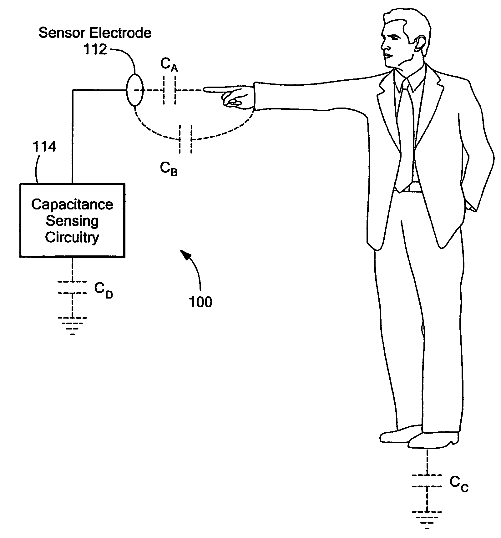
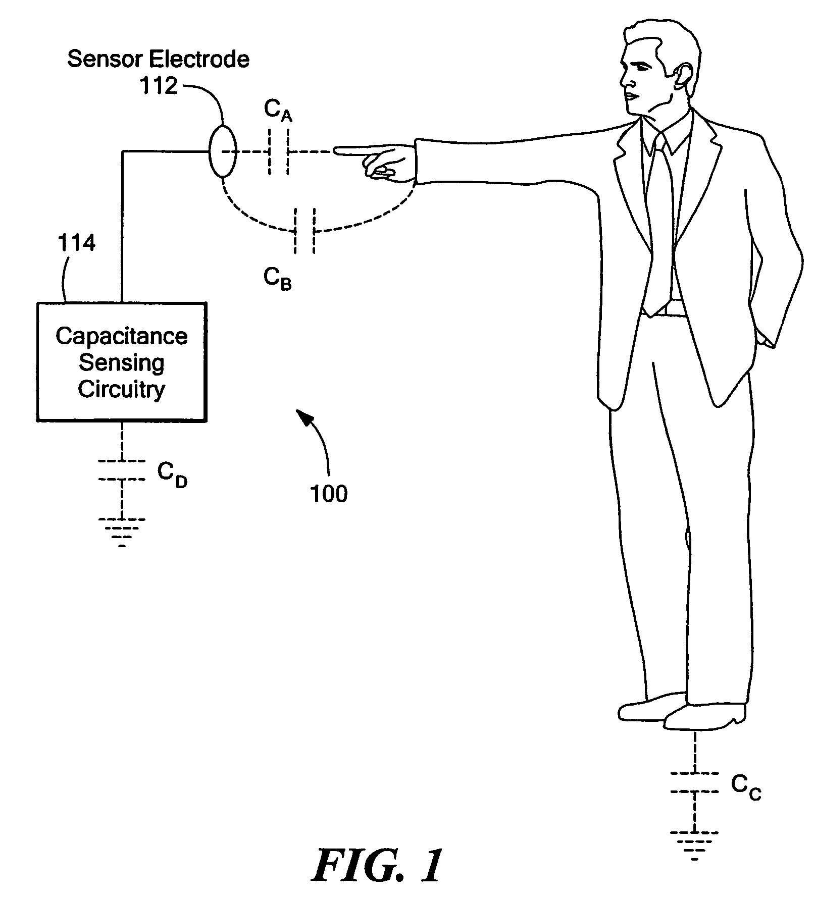
However, if the capacitance-based proximity detector 100 has reduced sensitivity, then the proximity detector 100 may be inoperable due to the inability to detect the small amount of capacitance between the finger of a user and the sensor electrode 112 at a reasonable distance.
Although the touch sensor of the '611 patent is configured to perform a differential measurement, the touch sensor does not operate by measuring capacitance.
The touch sensor disclosed in the '611 patent has drawbacks, however, when used to implement a touchless switch.
This interaction of electric fields is relatively complex because the two sensor electrodes and the object are at different voltage potentials, and there is no precise relationship governing the voltage difference between the sensor electrodes and the proximity of the object to the sensor electrodes.
Furthermore, the methods disclosed in the '611 patent to measure the voltage difference between the sensor electrodes are only effective if the voltage difference is significant enough as in the case of a touch switch.
Therefore, the approach disclosed in the '611 patent is not precise or sensitive enough to be used in a touchless switch.
The approach disclosed in the '477 patent also has drawbacks, however, in that it requires pulse signals, which can introduce transient noises and instability to the operational amplifier and can adversely affect the accuracy of the operational amplifier output.
Although low pass filters and a feedback capacitor may be employed at the inputs of the operational amplifier to mitigate the effects of transient noises and instability, the addition of such components adversely affects the accuracy and sensitivity of the capacitance detection circuitry.

Method used


Image

  • Linear capacitance measurement and touchless switch
  • Linear capacitance measurement and touchless switch
  • Linear capacitance measurement and touchless switch

Examples


Embodiment Construction

[0042]The entire disclosures of U.S. patent application Ser. No. 11 / 202,486 filed Aug. 12, 2005 entitled LINEAR CAPACITANCE MEASUREMENT AND TOUCHLESS SWITCH, U.S. Provisional Patent Application No. 60 / 690,486 filed Jun. 15, 2005 entitled LINEAR CAPACITANCE MEASUREMENT AND TOUCHLESS SWITCH, U.S. Provisional Patent Application No. 60 / 662,378 filed Mar. 17, 2005 entitled CAPACITANCE MEASUREMENT AND TOUCHLESS SWITCH, U.S. Provisional Patent Application No. 60 / 619,697 filed Oct. 19, 2004 entitled DIFFERENTIAL CAPACITANCE MEASUREMENT AND TOUCHLESS SWITCH, and U.S. Provisional Patent Application No. 60 / 601,610 filed Aug. 16, 2004 entitled DIFFERENTIAL CAPACITANCE MEASUREMENT AND TOUCHLESS SWITCH, are incorporated herein by reference.

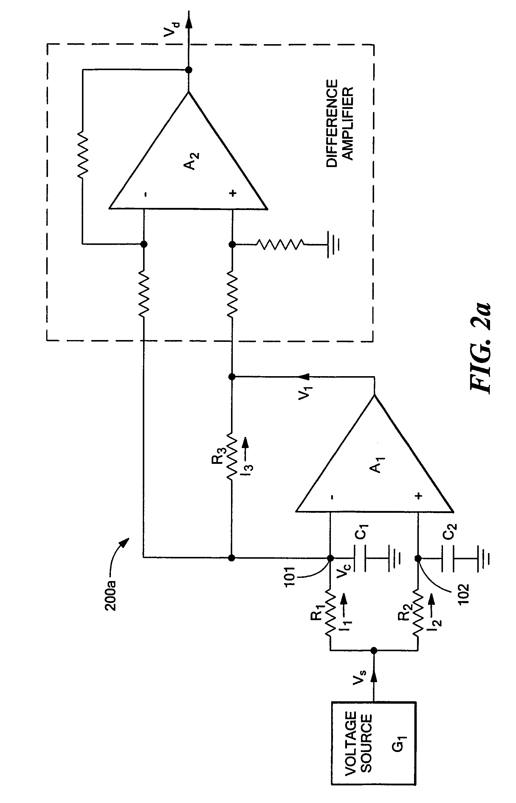
[0043]A capacitance measurement apparatus and technique are disclosed that can be employed to enhance the sensitivity and accuracy of many different types of capacitive transducers, proximity sensors, and touchless switches. FIG. 2a depicts a first illustrative...


PUM


Abstract

Capacitance measurement apparatus that enhances the sensitivity and accuracy of capacitive transducers, proximity sensors, and touchless switches. Each of two capacitors (C1, C2) under measurement has one end connected to ground and is kept at substantially the same voltage potential by operational amplifier (A1) or amplifiers (A0, A1) using negative feedback. The apparatus is driven by a periodic e.g. sinusoidal signal source (G1) or sources (G1, G2) and includes a difference amplifier (A2) operative to produce an electrical signal having a linear relationship with a specified arithmetic function of the capacitances of the two capacitors (C1, C2). A touchless switch is implemented using the capacitance measurement apparatus. The touchless switch includes two sensor electrodes (E1, E2) that correspond to the two capacitors (C1, C2) under measurement and in one embodiment has a front surface in the form of a container.

Description

CROSS REFERENCE TO RELATED APPLICATIONS[0001]This application is a continuation-in-part (CIP) application of prior U.S. patent application Ser. No. 11 / 202,486 filed Aug. 12, 2005 entitled LINEAR CAPACITANCE MEASUREMENT AND TOUCHLESS SWITCH, now U.S. Pat. No. 7,323,886. This application claims benefit of U.S. Provisional Patent Application No. 60 / 690,486 filed Jun. 15, 2005 entitled LINEAR CAPACITANCE MEASUREMENT AND TOUCHLESS SWITCH, U.S. Provisional Patent Application No. 60 / 662,378 filed Mar. 17, 2005 entitled CAPACITANCE MEASUREMENT AND TOUCHLESS SWITCH, U.S. Provisional Patent Application No. 60 / 619,697 filed Oct. 19, 2004 entitled DIFFERENTIAL CAPACITANCE MEASUREMENT AND TOUCHLESS SWITCH, and U.S. Provisional Patent Application No. 60 / 601,610 filed Aug. 16, 2004 entitled DIFFERENTIAL CAPACITANCE MEASUREMENT AND TOUCHLESS SWITCH.STATEMENT REGARDING FEDERALLY SPONSORED RESEARCH OR DEVELOPMENT[0002]Not applicableBACKGROUND OF THE INVENTION[0003]The present invention relates genera...

Claims


Application Information

Patent Timeline
Patent Type & Authority Patents(United States)
IPC IPC(8): G01R27/26
CPCH03K17/962H03K2017/9602H03K2217/960745
Inventor LEE, YING LAU
Owner LEE YING LAU
Learn More