

Micro-impact testing apparatus
a micro-impact and testing apparatus technology, applied in the direction of material strength using single impulsive force, instruments, material analysis, etc., can solve the problems of not being cost effective when done solely for testing purposes, and affecting the efficiency of the process
- Summary
- Abstract
- Description
- Claims
- Application Information
AI Technical Summary
Benefits of technology
Problems solved by technology
Method used
Image

Examples
Embodiment Construction
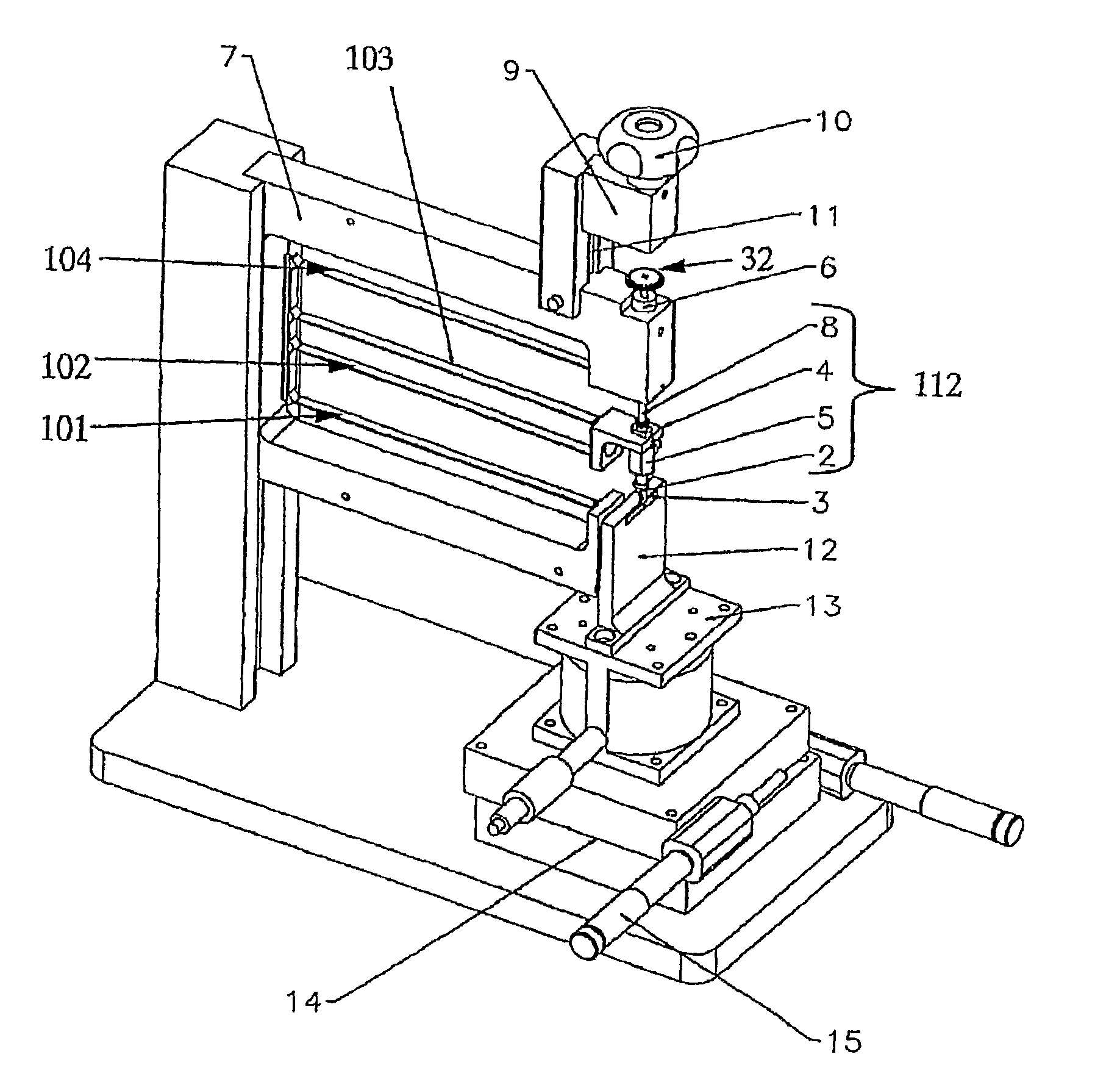
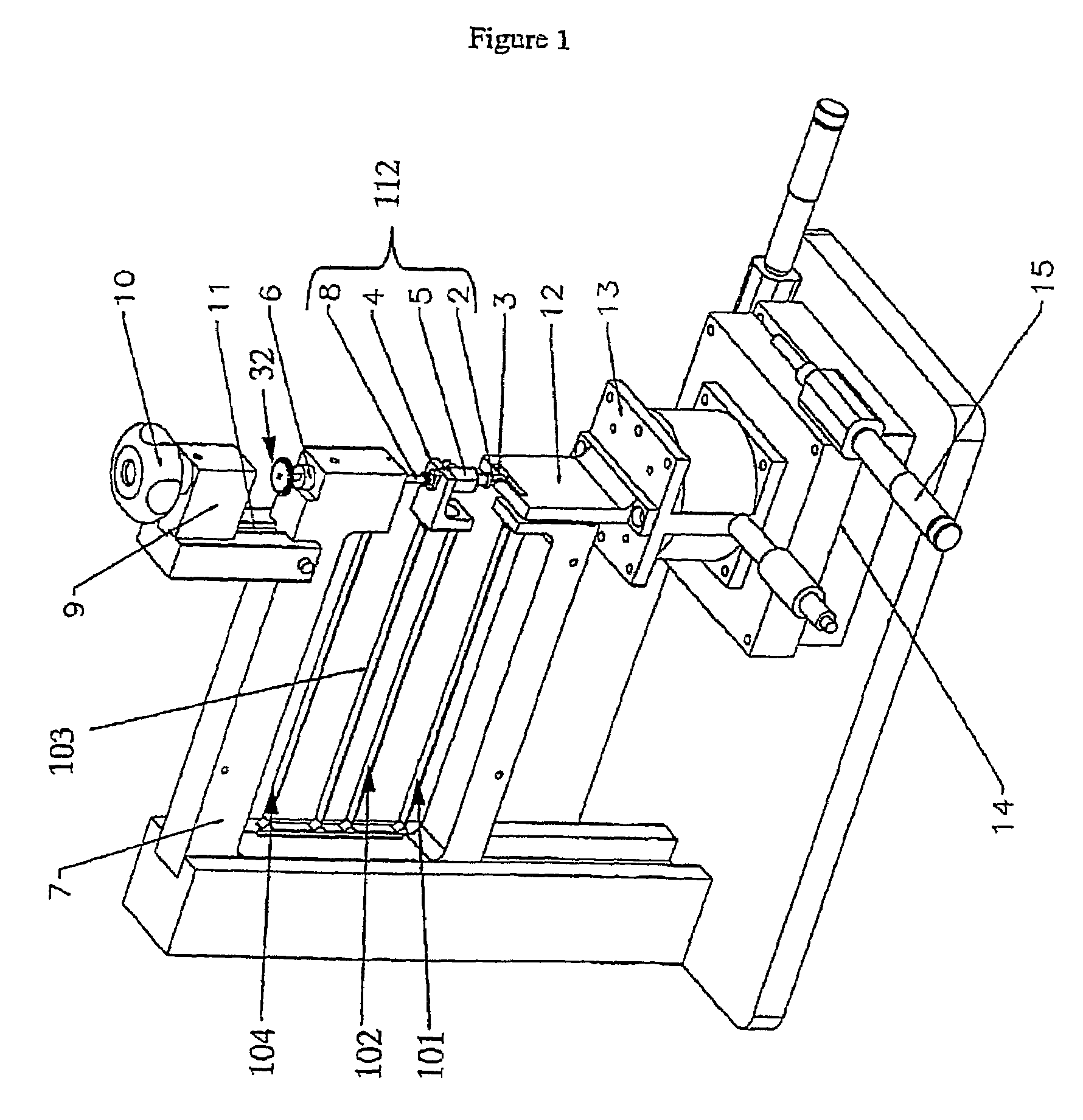
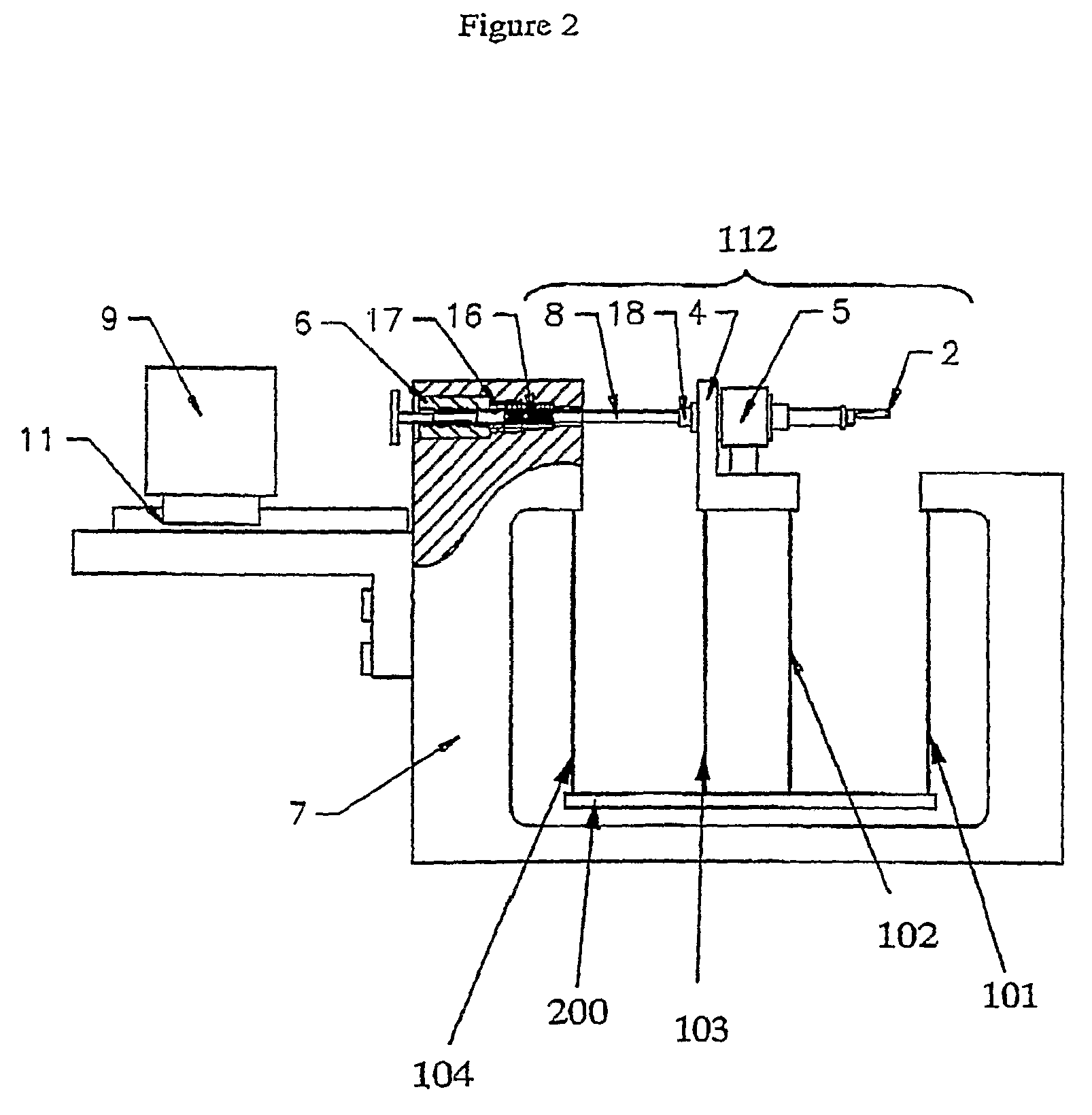
[0010]The impact head, according to the above embodiment of the impact testing apparatus, is moveable transversally with respect to the first and second flexural springs along a linear line between a spring-loaded position (loaded position) and an impact position thereof. Further, the specimen holder is aligned with the impact device such that the test specimen received in said test specimen holder is arranged in said impact position of the impact head. This enables the impact head to precisely impact the specimen after traveling from its loaded position towards its impact position along said linear line. The linear motion is important in order for the impact head to provide for the required precise shear force to the test specimen upon release. The linear motion of the impact head is also necessary to enable the testing apparatus to carry out tests on test specimens of minute size and geometry.
[0011]In addition, further advantages of using the above-mentioned arrangement, including...
PUM
 Abstract
Description
Claims
Application Information