Roller stop for coverings for architectural openings

a technology for architectural openings and roller stops, which is applied in the direction of curtain suspension devices, shutters/movable grilles, door/window protective devices, etc., can solve the problems of fabric soot, and achieve the effect of preventing further rotation of the rollers

Active Publication Date: 2009-03-10
HUNTER DOUGLAS INC
View PDF19 Cites 58 Cited by
  • Summary
  • Abstract
  • Description
  • Claims
  • Application Information

AI Technical Summary

Benefits of technology

[0009]The roller stop of the present invention comprises a main body and a secondary body that are made of a substantially rigid material, but wherein the secondary body is pivotal relative to the main body. One of the main and secondary bodies includes a plurality of vertically disposed serrated teeth while the other of the main body and secondary body has a catch adapted to be selectively engaged between individual ones of the serrated teeth. The selected engagement of the catch with the serrated teeth determines the angular relationship of the main body relative to the secondary body thereby positively, but selectively positioning an abutment edge of the secondary body in closely adjacent but spaced relationship from the fabric when the fabric is fully wrapped on the roller for the covering. The abutment edge is adapted to engage a bottom rail connected to the lower edge of the fabric when the fabric is fully wrapped on the roller so as to prevent further rotation of the roller.

Problems solved by technology

Such a roller stop has not been without problems inasmuch as the hinge connection of the two elements has an objectionable noise factor and the constant contact of the second element with the shade material, as well as the repetitive raising and lowering of the shade, causes soiling of the fabric where the limit stop contacts the fabric.

Method used


Image

  • Roller stop for coverings for architectural openings
  • Roller stop for coverings for architectural openings
  • Roller stop for coverings for architectural openings

Examples


Embodiment Construction

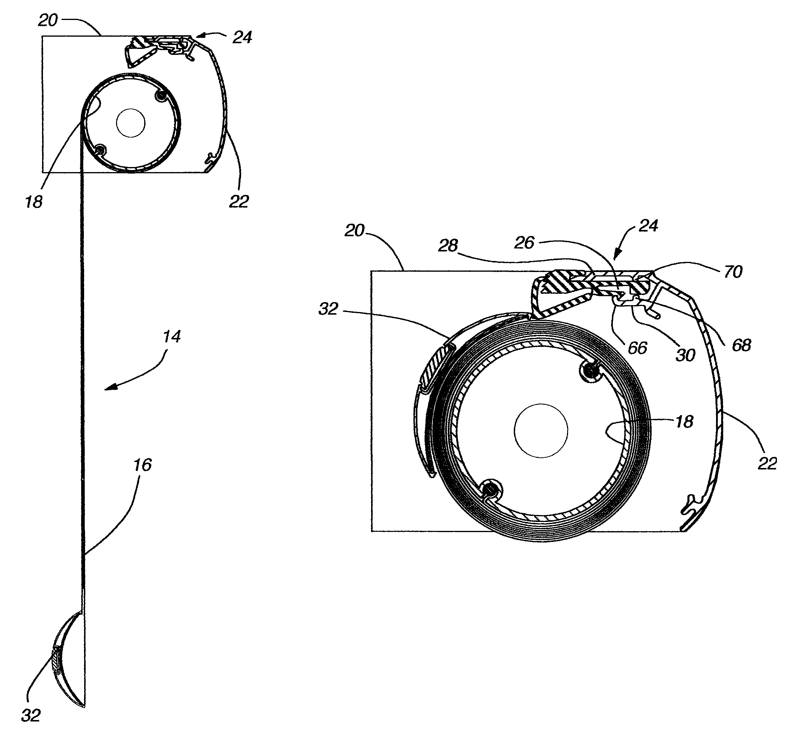
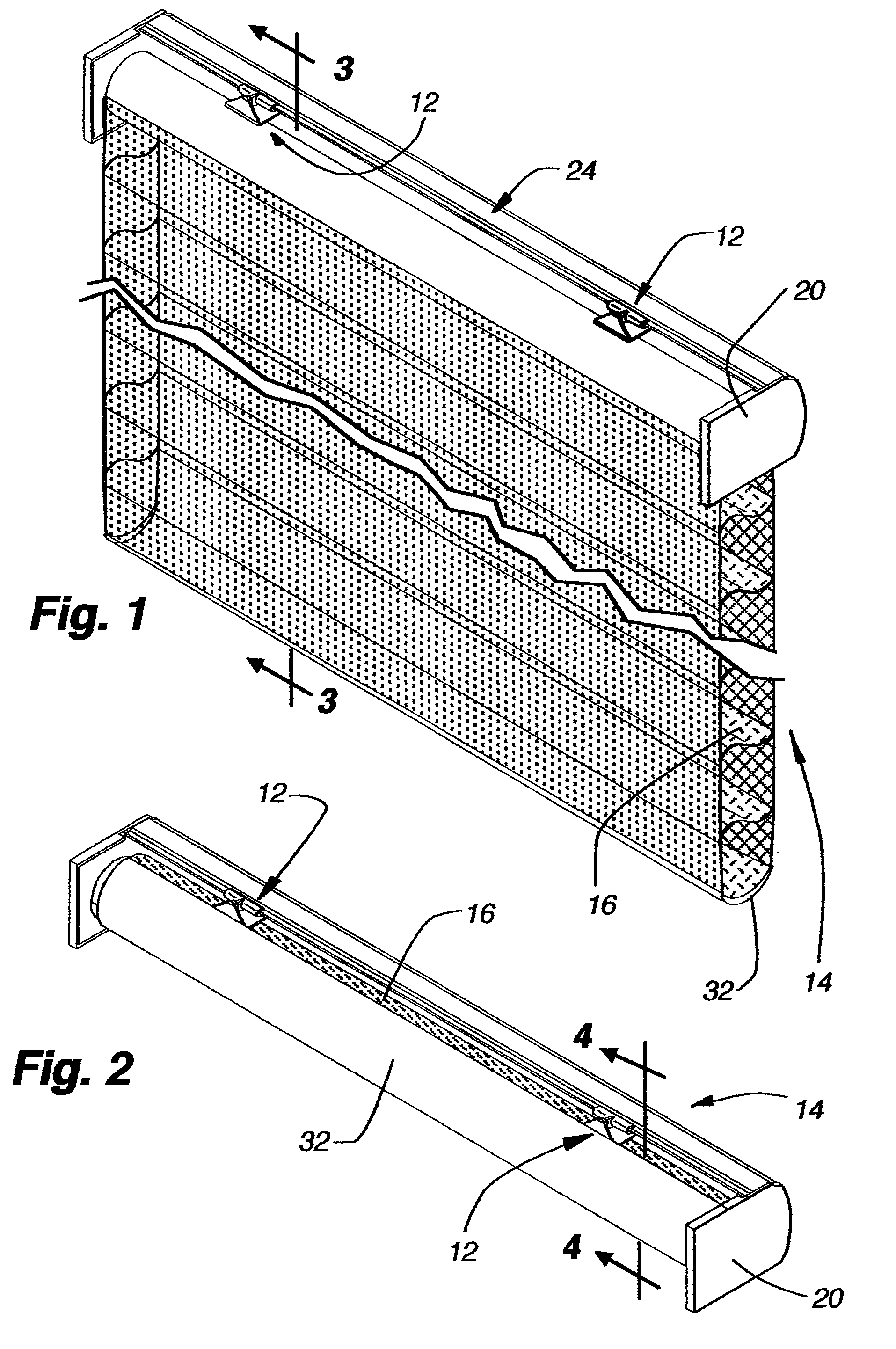
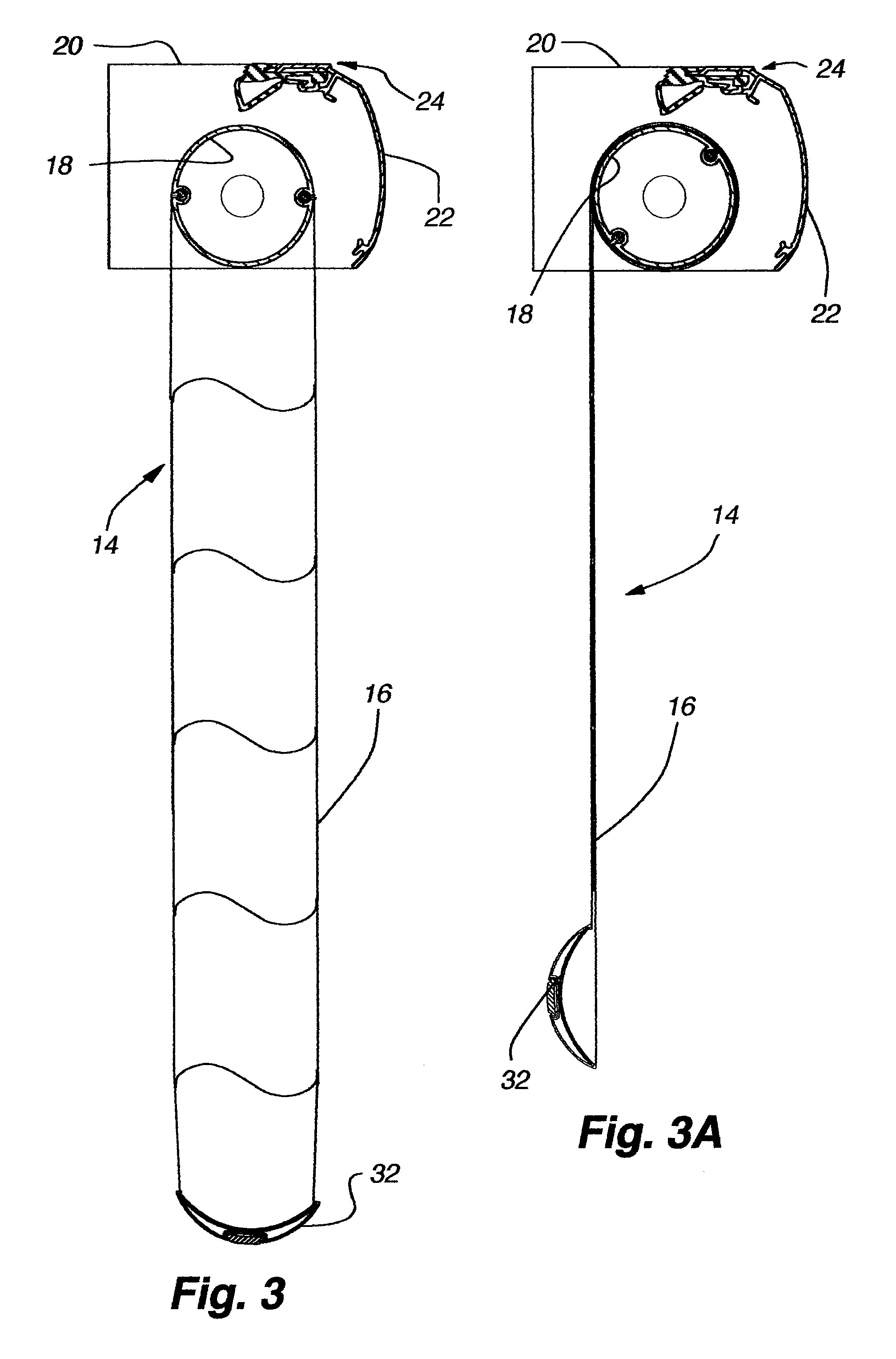
[0023]A pair of roller stops 12 in accordance with the present invention is seen in FIGS. 1 and 2 mounted on a conventional covering 14 for an architectural opening wherein the covering is a roll-up cellular shade including a shade material 16 and a roller 18 (FIGS. 3, 3A, 4 and 4A) on which the shade material can be wrapped or unwrapped in a retracted or extended position of the covering respectively. A conventional head rail 20 overlies the roller and shade material wrapped thereabout for aesthetic purposes and the head rail and roller are mounted on brackets not shown in as much as they are not pertinent to an understanding of the present invention. In fact, the shade material would not need to be a cellular shade material, but any shade material that is flexible and can be wrapped about a roller in a rollup shade. The head rail for the covering is important to an understanding of the present invention only in that the roller stops 12 are mountable on the head rail.

[0024]The head...


PUM


Abstract

A roller stop for connection to the head rail of a covering for an architectural openings is releasably connectable to a rear edge of the head rail in overlying relationship with a roller having shade material thereon with the shade material having a bottom rail. The roller stop has a pivotally mounted body selectively positionable in closely adjacent but spaced relationship from the outer wrap of shade material on the roller and in a position to engage the bottom rail when the shade material is fully wrapped on said roller. A catch arm is selectively engageable with serrated teeth to releasable hold the pivotal body in a preselected desired position.

Description

CROSS-REFERENCE TO RELATED APPLICATION[0001]The present application claims the benefit under 35 U.S.C. § 119(e) to U.S. Provisional Patent Application No. 60 / 725,026 (“the '026 application”), which was filed on Oct. 7, 2005 and entitled “Roller Stop For Coverings For Architectural Openings.” The '026 application is incorporated by reference into the present application in its entirety.BACKGROUND OF THE INVENTION[0002]1. Field of the Invention[0003]The present invention relates generally to coverings for architectural openings and more specifically to a roller stop adapted to limit the retracting rotation of a roller on which a shade material is mounted in an architectural opening.[0004]2. Description of the Relevant Art[0005]Generally, window coverings have various mechanical means for controlling the upper and lower positions of the fabric sheeting materials used in the covering. Such mechanical means is commonly referred to as a limit stop and when the sheeting material is mounted...

Claims


Application Information

Patent Timeline
Patent Type & Authority Patents(United States)
IPC IPC(8): E06B9/08
CPCE06B9/42E06B2009/2435E06B2009/802
Inventor SMITH, STEPHEN P.HOFFMANN, BRIAN M.
Owner HUNTER DOUGLAS INC
Why Eureka
Try Eureka