Fluid-storing container

a technology for storage containers and fluids, applied in the field of fluid storage containers, can solve the problems of inability to prevent the valve portion b>33/b> from inadequate tilting, and increase the manufacturing cost of the valve mechanism, so as to prevent fluid leakage, simple configuration, and simple structure

Inactive Publication Date: 2009-03-10
MASUDA MASATOSHI
View PDF35 Cites 11 Cited by
  • Summary
  • Abstract
  • Description
  • Claims
  • Application Information

AI Technical Summary

Benefits of technology

[0006]The present invention was accomplished to solve at least one or more of the above-mentioned problems. In an aspect, an object of the present invention is to provide a flexible fluid-storing container comprising a valve mechanism which can prevent a valve body from inadequately tilting while having a simple configuration. Another object of an embodiment of the present invention is to provide a fluid-storing container having a simple configuration and capable of preventing fluid leakage.
[0010]The guiding shaft may have a lower end engaging portion (e.g., 322b, 422b) which engages with a lower end (e.g., 312b, 412b) of the guiding portion to restrict upward movement of the guiding shaft.

Problems solved by technology

However, the valve mechanism which applies to the fluid-storing container described in Japanese Patent Laid-open No. 2004-059046 has no structure to prevent the valve portion 33 from inadequately tilting.
In this case, increase in manufacturing costs of the valve mechanism may be inevitable.

Method used


Image

  • Fluid-storing container
  • Fluid-storing container
  • Fluid-storing container

Examples


first embodiment

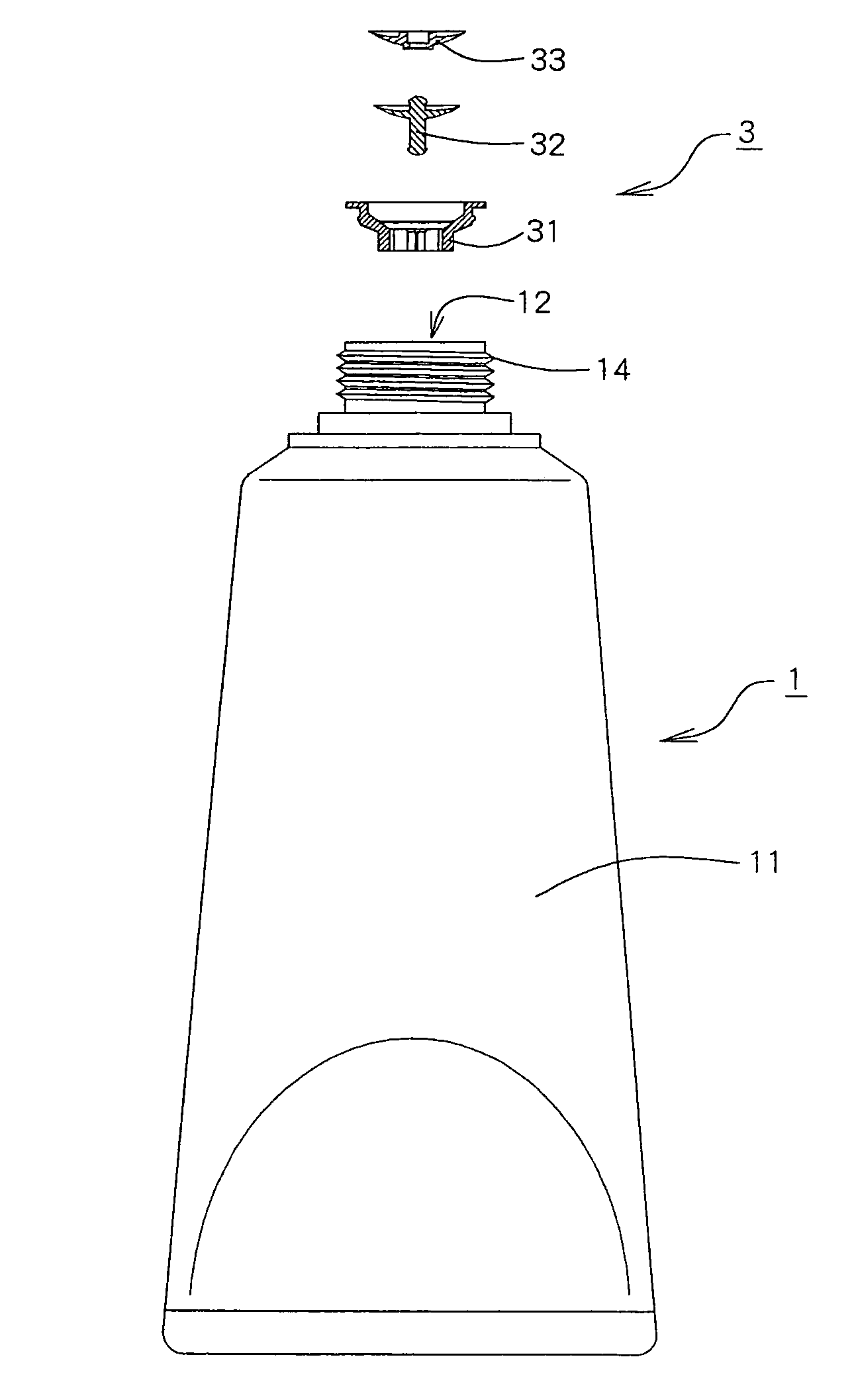
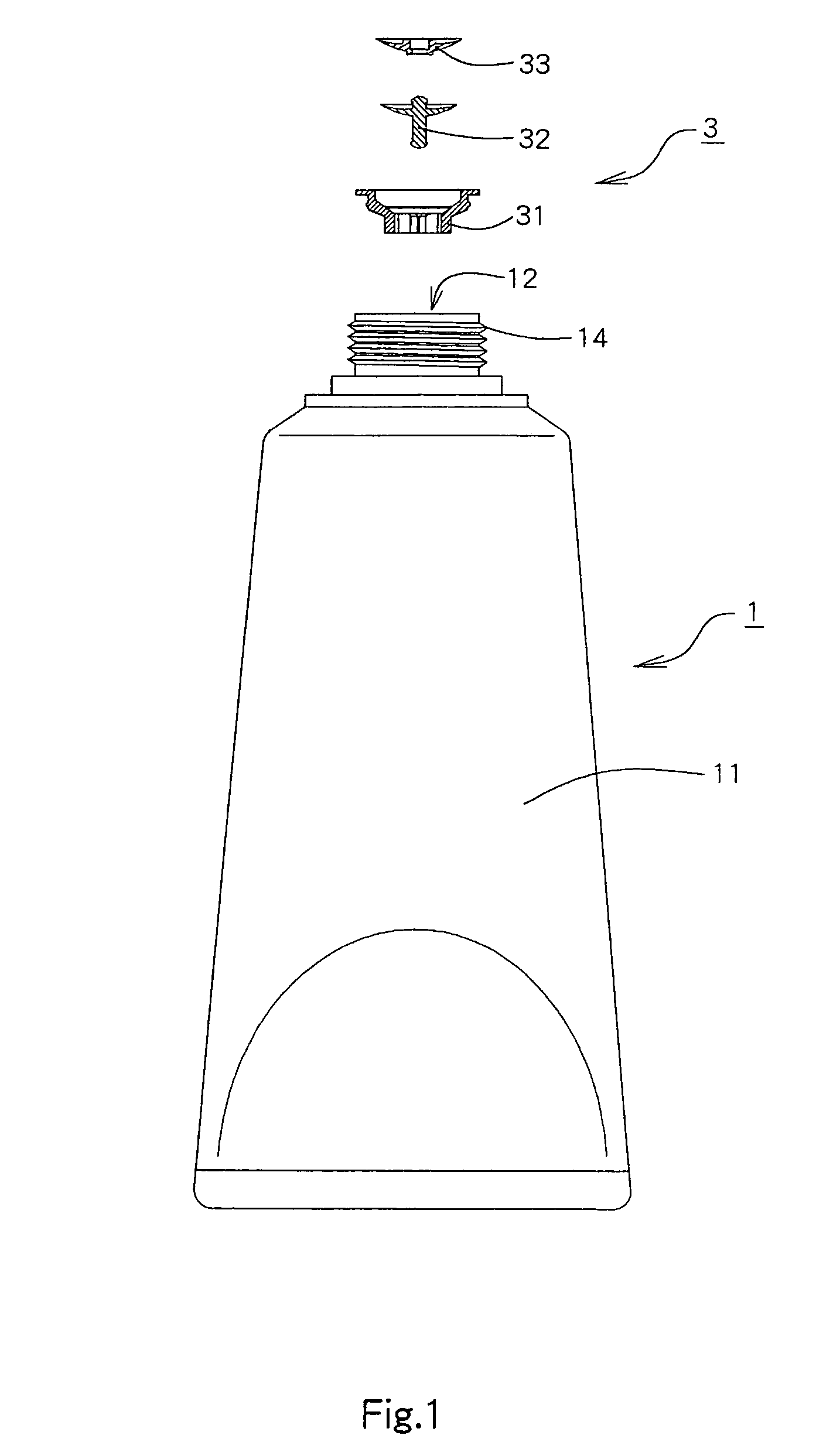
[0047]FIG. 1 is a longitudinal partially sectional view which shows a fluid-storing container according to the present invention by taking it apart to pieces.

[0048]This fluid-storing container may be used as a container for beauty products for storing gels such as hair gels and cleansing gels, creams such as nourishing creams and cold creams or liquids such as skin lotions used in the cosmetic field. Additionally, this fluid-storing container also can be used as a container for general medicines, solvents or foods, etc. In this specification, high-viscosity liquids, semifluids, gels that sol solidifies to a jelly, and creams and regular liquids are all referred to as fluids.

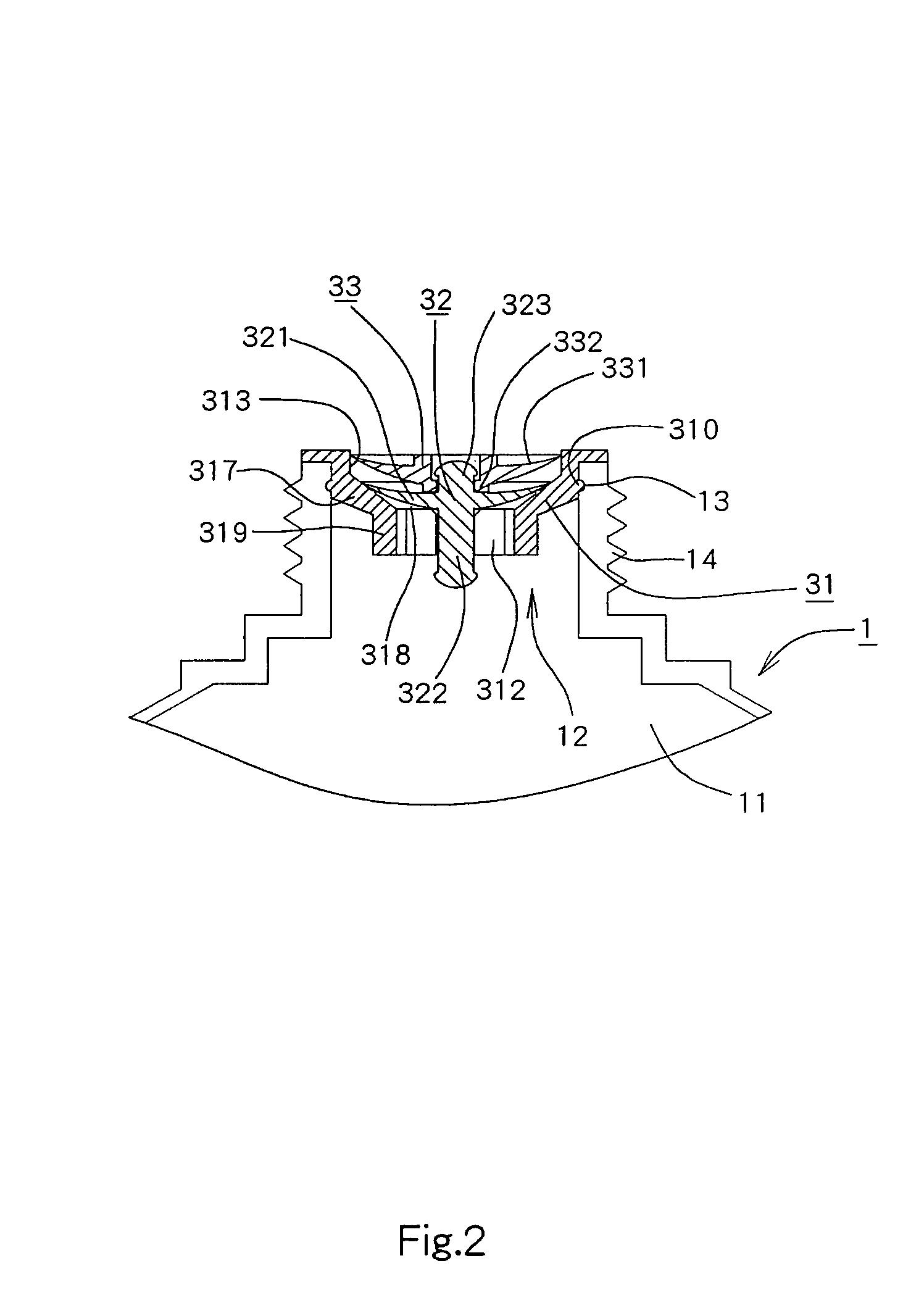
[0049]This fluid-storing container comprises a container main body and a valve mechanism 3.

[0050]A container main body 1 comprises a fluid-storing portion 11 for storing a fluid inside it, an opening portion 12 for discharging the fluid and being formed at an end of the fluid-storing portion, a concave portion 13...

second embodiment

[0083]FIG. 10 is a partial longitudinal sectional view which shows a fluid-storing container according to the present invention by taking it apart to pieces.

[0084]The fluid-storing container according to the second embodiment of the present invention uses a valve mechanism 4 in place of the valve mechanism 3 in the fluid-storing container according to the first embodiment of the present invention.

[0085]FIGS. 11 to 14 are longitudinal sectional views showing the valve mechanism 4 in the fluid-storing container according to the second embodiment of the present invention.

[0086]Additionally, of these figures, FIG. 11 shows a state in which the fluid-storing portion 11 is left without being pressed; FIG. 12 shows a state in which the valve mechanism 4 opens the opening portion 12 with the fluid-storing portion 11 being pressed; FIG. 13 shows a state in which a fluid remaining in the vicinity of the opening portion 12 is being sucked down into the fluid-storing portion 11 with a pressure ...


PUM


Abstract

A valve mechanism (3) includes a valve seat member (31) having a guiding portion (319); a valve member (32) having a valve body (321), a guiding shaft (322), and a supporting shaft (323); and a sub-valve member (33) having a sub-valve body (331) and a connecting portion (332). The valve body (321) and the sub-valve body (331) ascend together by pressing the fluid-storing portion (11); and the valve body (321) travels to an open position and the sub-valve body (331) travels to a detached position. In this state, when a pressure applied to the fluid-storing portion (11) is removed, the valve body (321) and the sub-valve body (331) descend together; and after the sub-valve body (331) travels to a contact position, the valve body (321) travels to a closed position.

Description

BACKGROUND OF THE INVENTION[0001]1. Field of the Invention[0002]The present invention generally relates to a fluid-storing container comprising a container main body which comprises a fluid-storing portion composed of a material having elastic resilience for storing a fluid therein, a mouth portion formed at an end of the fluid-storing portion for discharging the fluid, and a valve mechanism which can be attached to the mouth portion.[0003]2. Description of the Related Art[0004]As this type of fluid-storing container, a fluid-storing container described in Japanese Patent Laid-open No. 2004-059046 is known. The fluid-storing container is shown in FIG. 19, wherein a valve mechanism 3 which applies to a fluid-storing container comprises (i) a supporting portion 32 having a nearly tubular shape in the center of which an opening portion 31 constituting a valve seat is formed, (ii) a first connecting portion 34 installed upright on the side of a container main body 1 for an area in the s...

Claims


Application Information

Patent Timeline
Patent Type & Authority Patents(United States)
IPC IPC(8): B65D35/38
CPCB65D47/2075Y10T137/88054Y10T137/789B65D35/46
Inventor MASUDA, MASATOSHI
Owner MASUDA MASATOSHI
Why Eureka
Try Eureka