Dust-collectable mobile robotic vacuum cleaner

Inactive Publication Date: 2009-03-17
E SUPPLY INT
View PDF3 Cites 142 Cited by
  • Summary
  • Abstract
  • Description
  • Claims
  • Application Information

AI Technical Summary

Benefits of technology

[0008]Further, the dust guider includes a plurality of guiding portions and two bevels formed at two sides of a front end thereof respectively. While turning and encountering a barrier, the robotic vacuum cleaner can slidably move over and across the barrie

Problems solved by technology

Thus, the conventional antonymous floor-cleaning

Method used


Image

  • Dust-collectable mobile robotic vacuum cleaner
  • Dust-collectable mobile robotic vacuum cleaner
  • Dust-collectable mobile robotic vacuum cleaner

Examples


Embodiment Construction

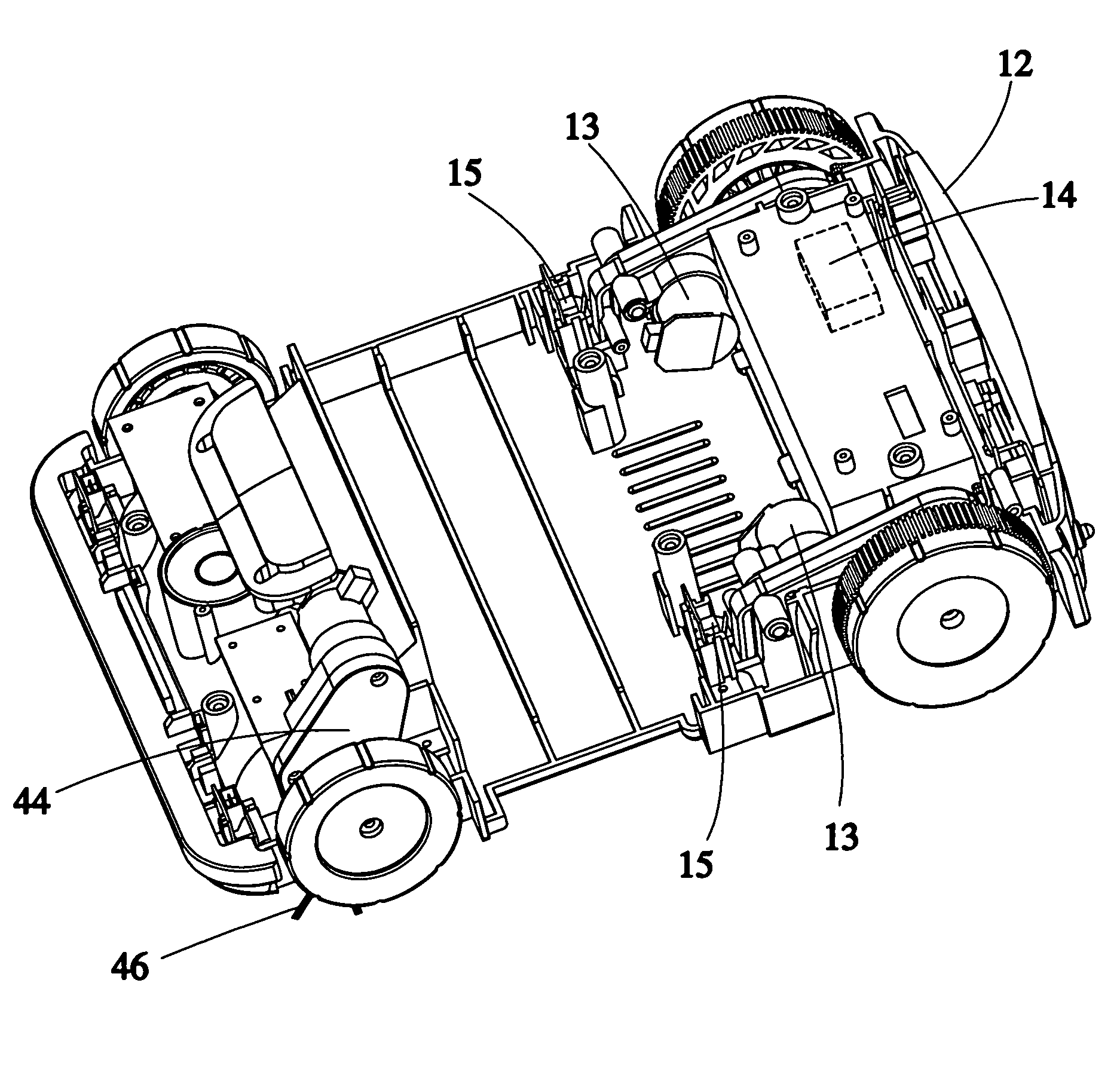
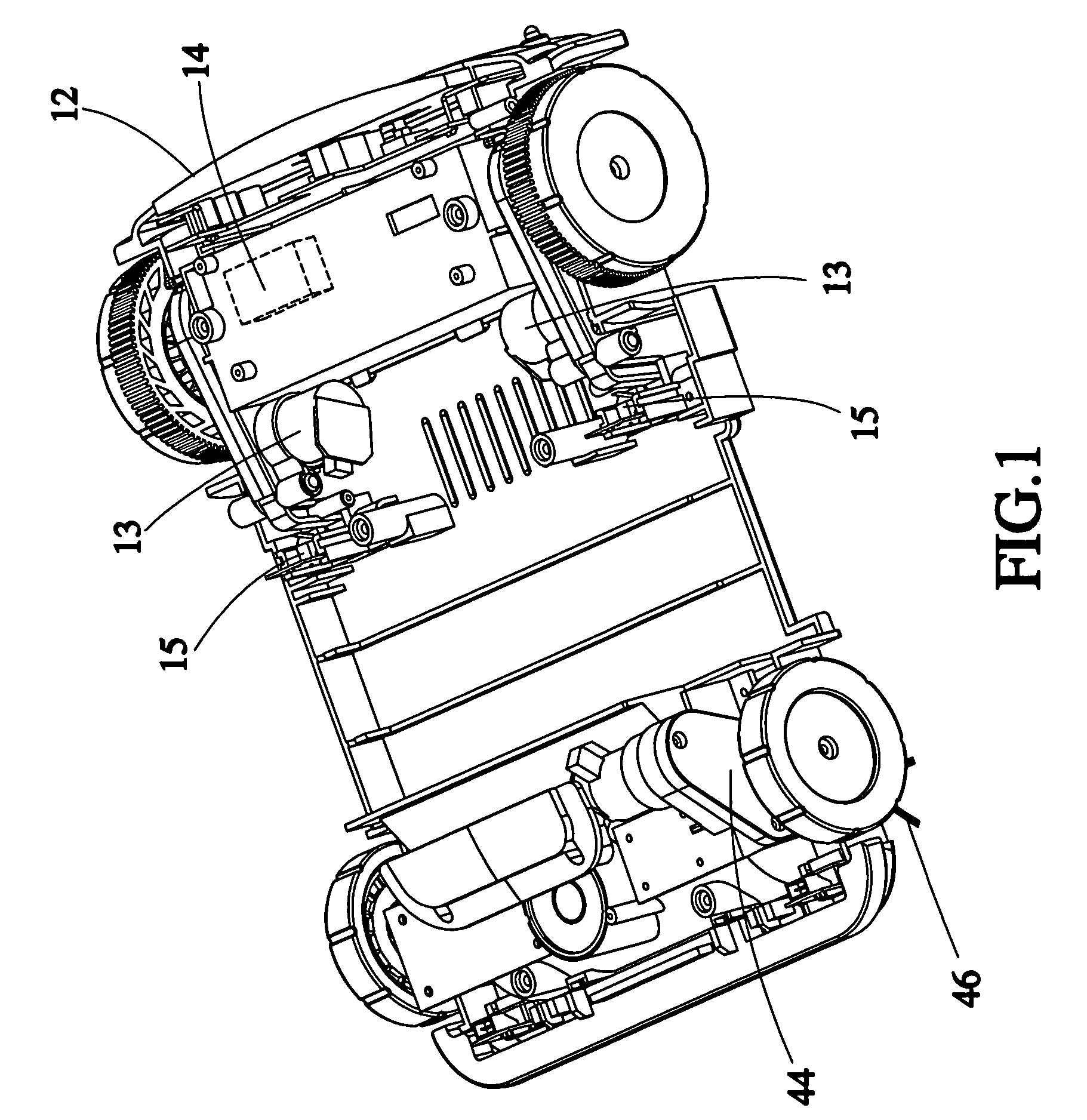
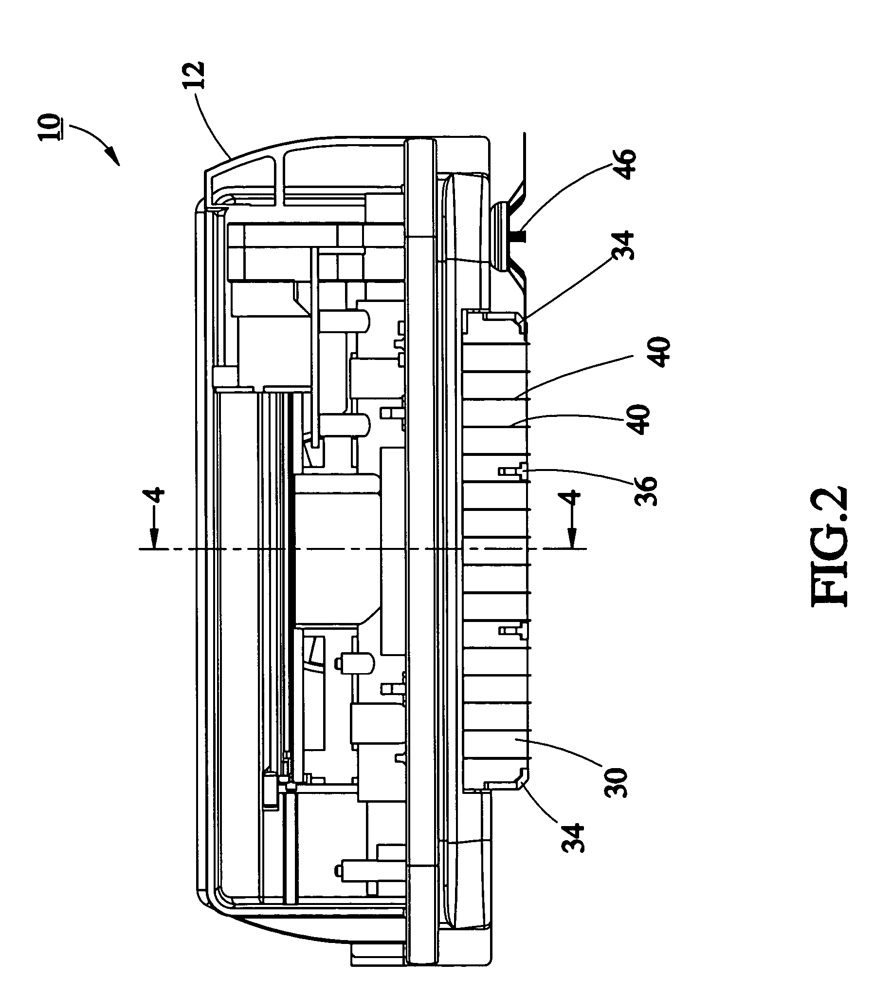
[0016]Referring to FIGS. 1-6, a dust-collectable mobile robotic vacuum cleaner 10 is composed of a base frame 12, a driving device 13, a control device 14, a collision-detectable unit 15, and a dust-collecting device 11. The driving device 13 is mounted to the base frame 12 for driving the movement of the base frame 12. The control device 14 is mounted to the base frame 12 and connected with the driving device 13 for controlling the moving direction of the driving device. The collision-detectable unit 15 is mounted to the base frame 12 and electrically connected with the control device 14 for detecting whether the base frame 12 in motion encounters a barrier and for generating and transmitting a signal to the control device 14 while encountering the barrier. The dust-collecting device 11 includes a dust-collecting box 20, a dust guider 30, and a round brush 40, a motor 42 for driving the round brush 40, a transmission 44 connected with the motor 42, and a side brush 46 connected wit...


PUM


Abstract

A dust-collectable mobile robotic vacuum cleaner includes a base frame, a driving device mounted to the base frame, a control device mounted to the base frame and electrically connected with the driving device, a collision-detectable unit mounted to the base frame electrically connected with the control device, and a dust-collecting device mounted to the base frame. The dust-collecting device has dust-collecting box, a dust guider, a round brush, and a dust entrance formed at one side of the dust-collecting box. The dust guider is located at a lower edge of the dust entrance, having two opposite sides pivotably mounted to the dust-collecting box and lying against the ground at a predetermined angle respectively, for upward and downward pivoting movement. The round brush is rotatably located at a front end of the dust guider for sweeping dust particles.

Description

BACKGROUND OF THE INVENTION[0001]1. Field of the Invention[0002]The present invention relates generally to mobile robotic vacuum cleaners, and more particularly, to a dust-collectable mobile robotic vacuum cleaner.[0003]2. Description of the Related Art[0004]As disclosed in U.S. Pat. No. 6,883,201, an antonymous floor-cleaning robot is composed of a brush assembly, a vacuum system, and a dust-collecting box, for sweeping and collecting dust particles. The brush assembly includes two round brushes parallel to each other. While the antonymous floor-cleaning robot is operated, the two round brushes roll in counter-direction to capture the dust particles away from the ground and then the vacuum system sucks the dust particles into the dust-collecting box.[0005]However, as shown in FIG. 7, a dead angle 2 is formed among the two round brushes 1 and the ground. While doing cleaning operation, the antonymous floor-cleaning robot fails to clean the dust particles located at the dead angle 2....

Claims


Application Information

Patent Timeline
IPC IPC(8): A47L5/00
CPCA47L5/30E01H1/0854A47L2201/00
Inventor LIN, WEN-HSU
Owner E SUPPLY INT
Why Eureka
Try Eureka