Translating multifocal ophthalmic lenses

a technology of ophthalmology and multifocal lens, which is applied in the field of ophthalmology, can solve the problems of large vertical distance that the lens must move, the difference in magnification between the near and the distance vision zone, and the eye is less able to accommodate or bend the natural lens,

Active Publication Date: 2009-03-17
JOHNSON & JOHNSON VISION CARE INC
View PDF18 Cites 74 Cited by
  • Summary
  • Abstract
  • Description
  • Claims
  • Application Information

AI Technical Summary

Benefits of technology

[0015]In one embodiment of the lenses of the invention, one surface of the lens, preferably the convex or anterior surface, has a central optic zone with at least two distance vision zones along with at least one near vision zone. The lenses of the invention are designed so that the distance power within the pupil area, or area overlaying the lens wearer's pupil while the lens is on-eye, composes greater than 50% of the corrective power in the pupil area in the superior portion of the optic zone, meaning the portion at or above the 0-180 degree, or horizontal, meridian, and less than 50% below the 0-180 degree meridian. Additionally, the location of the zones is such as to minimize the impact of pupil size in ability to access a zone.

Problems solved by technology

As an individual ages, the eye is less able to accommodate, or bend the natural lens, to focus on objects that are relatively near to the observer.
Conventional translating contact lenses are disadvantageous in that the vertical distance that the lens must move is large given that the lenses incorporate only a distance and near vision zone.
Yet another disadvantage of the conventional lenses is that the difference in magnification between the near and distance vision zones will produce an effect in which the viewed image appears to “jump” as one moves from distance to near vision zones.

Method used


Image

  • Translating multifocal ophthalmic lenses
  • Translating multifocal ophthalmic lenses
  • Translating multifocal ophthalmic lenses

Examples


example 1

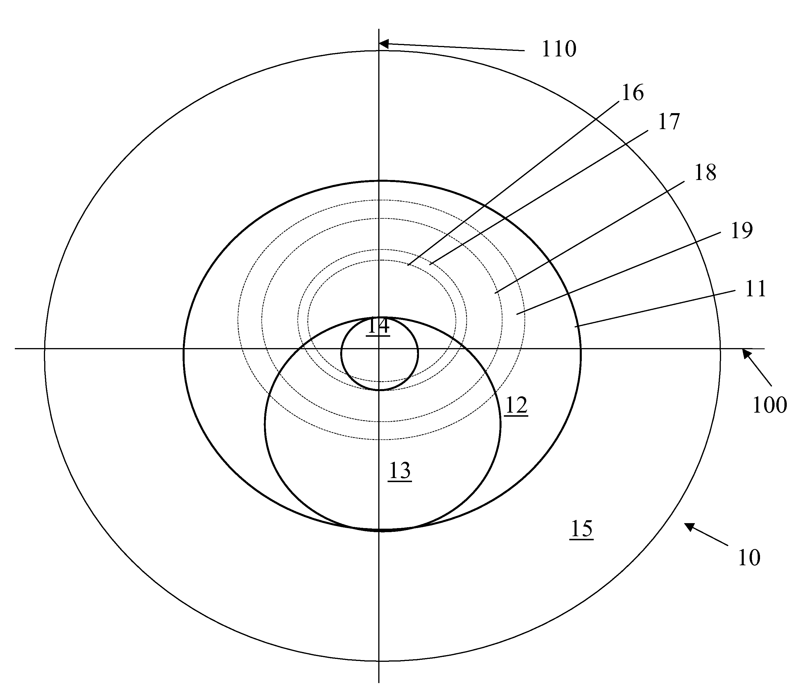
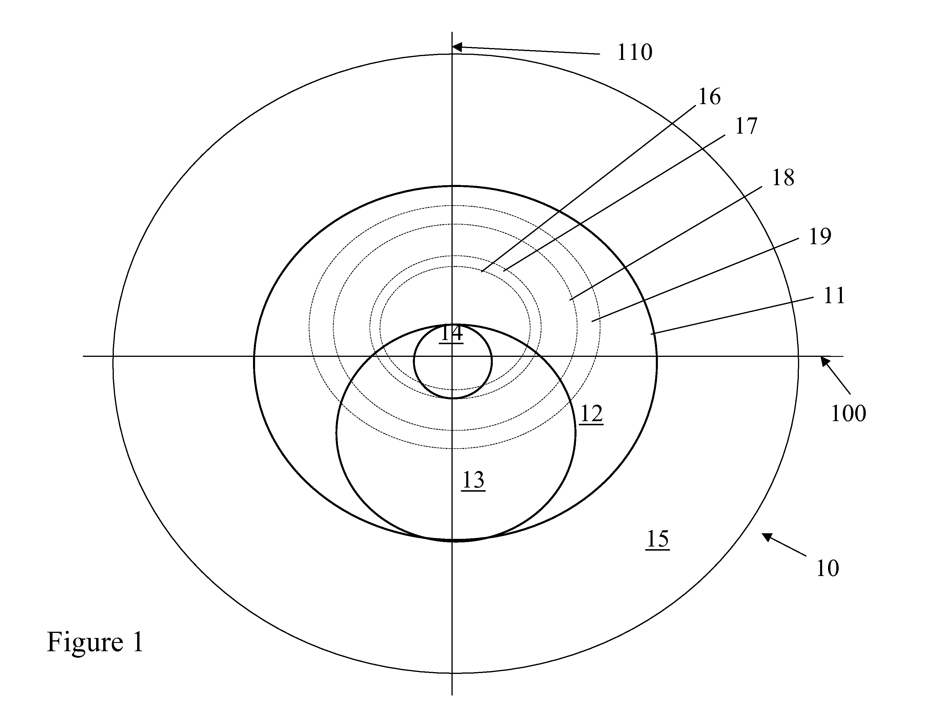
[0029]A lens in accordance with FIG. 1 is provided. Referring to FIG. 1, optic zone 11 has an outer distance vision zone 12 with a diameter of 8 mm and an inner distance vision zone 14 with a diameter of 1.60 mm. Near vision zone 13 is 1.60 mm in diameter. Dotted lines 16, 17, 18 and 19 represent pupils of diameters of 3.0, 3.5, 5.0 and 6.0 mm, respectively.

[0030]The distance percentage within the pupil area was calculated for each pupil size and at pupil locations of y=0 and y=−1.5 mm from a distance reference point that is located at y=0.8 mm, meaning a point along the 90-270 degree meridian that is 0.8 mm superiorly from the 0-180 degree meridian. The results in Table 1 demonstrate that the lens design produces a pupil independent distance percentage for both y=0 and y=−1.5 mm meaning that, at y=0, the distance percentage is >50 &, at y=−1.5, is <50%, and the percentages are relatively constant with pupil size.

[0031]

TABLE 1Example 13.0 mm3.5 mm5.0 mm6.0 mmAverage  0.0 mm90%80%73%...

example 2

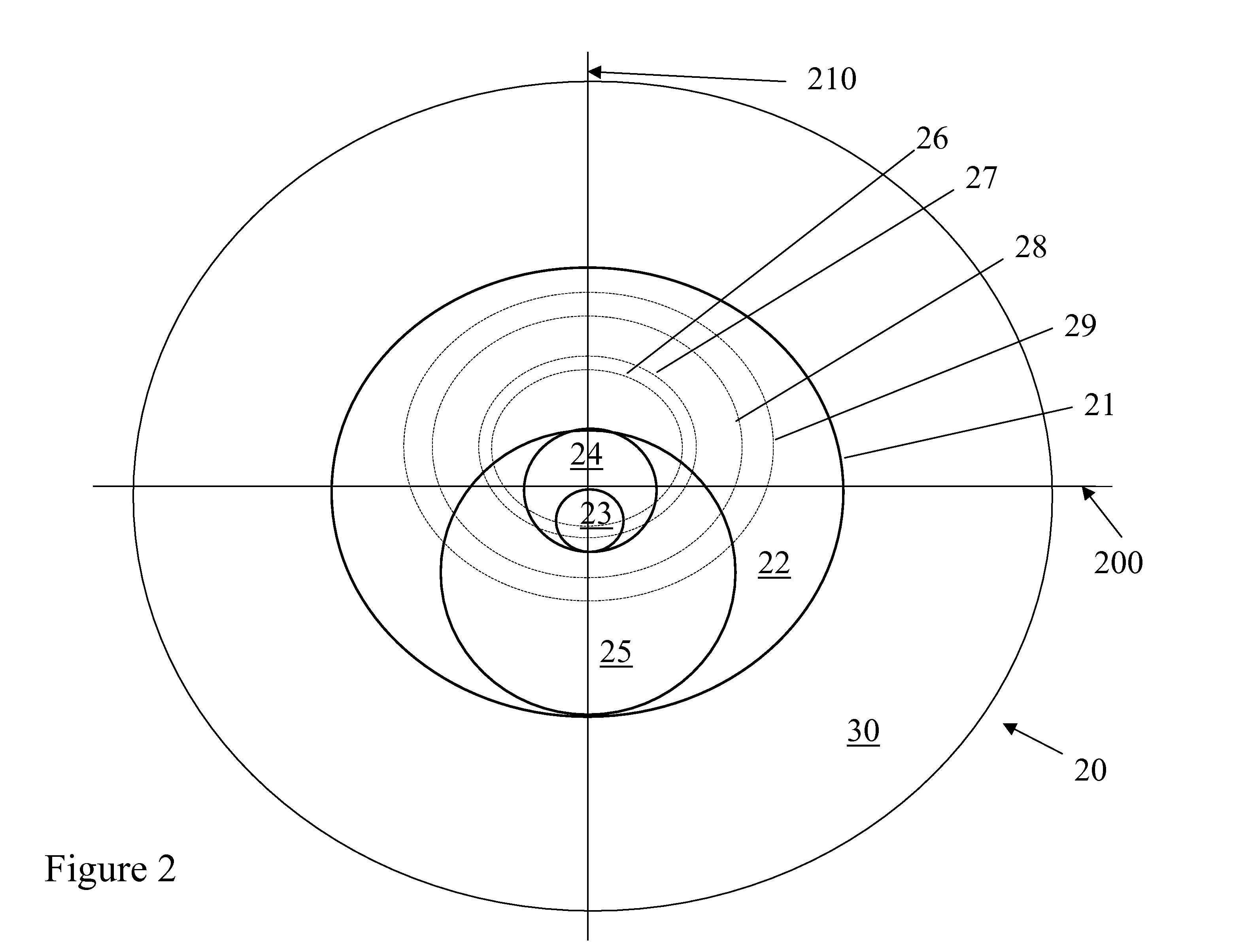
[0032]A lens in accordance with FIG. 2 is provided. Referring to FIG. 2, optic zone 21 has an outer distance vision zone 22 with a diameter of 8 mm and an inner distance vision zone 24 with a diameter 2.10 mm. An inner near vision zone 23 is of a diameter of 1.04 mm and an outer near vision zone 25 is of a diameter of 4.74 mm. Dotted lines 26, 27, 28 and 29 represent pupils of diameters of 3.0, 3.5, 5.0 and 6.0 mm, respectively.

[0033]The pupil sizes are analyzed for the percentage of distance power within the pupil area at y=0 and y=−1.5 for the distance reference point of y=0.8 mm. The results in Table 2 demonstrate that the lens design produces a pupil independent distance to near ratio for y=0 and y=1.5.

[0034]

TABLE 2Example 23.0 mm3.5 mm5.0 mm6.0 mmAverage  0.0 mm80%75%71%67%73%−1.5 mm25%25%29%38%30%


PUM


Abstract

The invention provides translating, multifocal lenses that are pupil insensitive or independent.

Description

FIELD OF THE INVENTION[0001]The invention relates to ophthalmic lenses. In particular, the invention provides lenses that provide more than one optical power, or focal length, and are useful in the correction of presbyopia.BACKGROUND OF THE INVENTION[0002]As an individual ages, the eye is less able to accommodate, or bend the natural lens, to focus on objects that are relatively near to the observer. This condition is known as presbyopia. Among the methods used to correct presbyopia is the providing of contact lenses incorporating both near and distance vision correction on each contact lens worn by the individual. In one type of such lenses, the distance and near vision regions are concentrically arranged around the geometric center of the lens. In another type of lens, a segmented lens, the near and distance vision regions are not concentric about the geometric center of the lens. In this type of lens, the majority of the near vision portion is located below the 0-180 degree, or h...

Claims


Application Information

Patent Timeline
Patent Type & Authority Patents(United States)
IPC IPC(8): G02C7/04G02C7/06
CPCG02C7/027G02C7/043G02C7/044G02C7/048G02C7/04A61F9/00G02C7/02
Inventor MENEZES, EDGAR V.
Owner JOHNSON & JOHNSON VISION CARE INC
Why Eureka
Try Eureka