Self-adjusting and centering camera mount for inspecting pipe

a camera mount and camera technology, applied in the direction of material analysis using wave/particle radiation, instruments, television systems, etc., can solve the problems of difficult advance or withdrawal from the pipe, blockage, and considerable friction in the pipe inserting of these devices, and achieve the effect of easy insertion through the pipe and easy retrieval

Active Publication Date: 2009-03-17
CAVALLERO PLASTICS
View PDF22 Cites 38 Cited by
  • Summary
  • Abstract
  • Description
  • Claims
  • Application Information

AI Technical Summary

Benefits of technology

[0009]It is an advantage of the present invention that it is easily pushed through a pipe.
[0010]It is yet another advantage of the present invention that it is easily retrieved from within the pipe.
[0011]It is a further advantage of the present invention that the camera is protected by the inner cylinder.
[0012]It is a fe...

Problems solved by technology

While these prior devices have worked adequately, they often encounter difficulties in that there is often considerable friction in inserting these devices into pipes.
Additionally, often the fixed sleds snag or catch irregularities in the pipe and are difficult to advance or withdraw from the pipe.
They often ...

Method used


Image

  • Self-adjusting and centering camera mount for inspecting pipe
  • Self-adjusting and centering camera mount for inspecting pipe
  • Self-adjusting and centering camera mount for inspecting pipe

Examples


Embodiment Construction

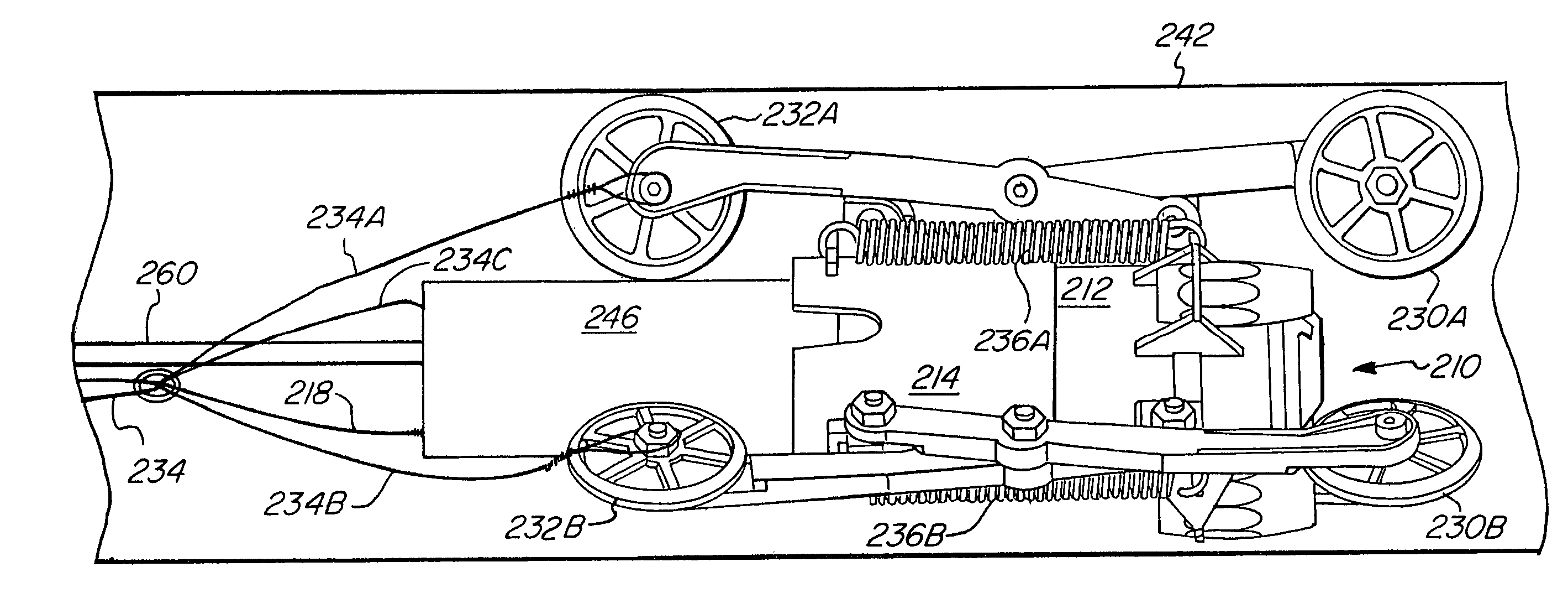
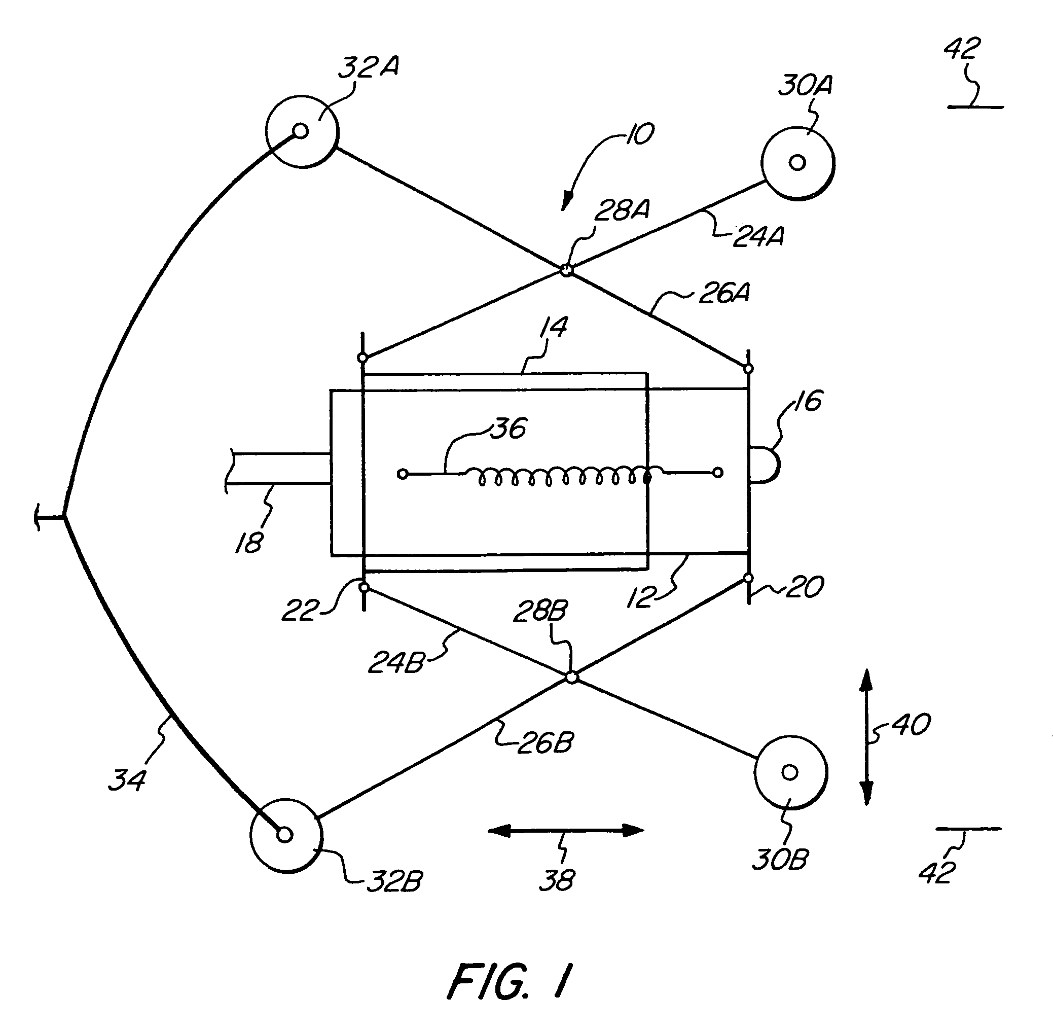
[0025]FIG. 1 schematically illustrates the camera mount 10 of the present invention. The camera mount 10 of the present invention is used to place a camera in pipes of different diameters. The camera mount 10 is self-adjusting so as to always center the camera within the pipe and to automatically adjust for different sized pipes. The camera mount 10 is comprised of an inner housing or an inner cylinder 12 and an outer housing or outer cylinder 14 that are slidably engaged with each other. A camera 16 is mounted within the inner cylinder 12 at one end. Power and video cables 18 extends out of the other end of the inner cylinder 12. The power and video cables 18 may be sufficiently rigid to force the camera mount 10 forward within a pipe 42. A flange 20 is placed on the inner cylinder 12 and is used for attaching a leg 26A and a leg 26B. The legs are pivotally attached to the flange 20. A flange 22 is attached to the outer cylinder 14. The flange 22 is used to pivotally attach second ...


PUM


Abstract

A mount for traveling within a pipe to center a tool, such as a camera, within the pipe. Inner and outer concentric cylinders are slidably nested. Pivoted leg pairs have one end connected to the outer cylinder and another end connected to the inner cylinder. The pivoted leg pairs move radially inward or outward as the inner and outer cylinder move axially with respect to each other. A spring biases wheels attached to the distal end of the pivoted leg pairs radially outward. The mount centers the inner and outer cylinder within the pipe and automatically adjusts to different diameters of pipes. The mount overcomes obstructions within the pipe and is easily retrievable. The interior of the pipe may be inspected or worked upon.

Description

RELATED APPLICATION[0001]This application claims the benefit of U.S. Provisional Application No. 60 / 545,178, filed Feb. 17, 2004.FIELD OF THE INVENTION[0002]The present invention relates in general to the snaking of a camera in a pipe to visually inspect the pipe, and particularly to a camera mount that centers the camera within the pipe and automatically adjusts to different size pipes.BACKGROUND OF THE INVENTION[0003]In many applications such as plumbing, it is often necessary to inspect pipes that are not readily accessible. This is commonly done by inserting into the pipe a camera so that the interior of the pipe can be remotely viewed and inspected. Typically, a camera is mounted onto a sled or frame having flexible wires or whiskers that fit within the interior diameter of the pipe being inspected. While these prior devices have worked adequately, they often encounter difficulties in that there is often considerable friction in inserting these devices into pipes. Additionally,...

Claims


Application Information

Patent Timeline
IPC IPC(8): H04N7/18B08B9/02F16L45/00F16L55/44H04N5/225
CPCB08B9/043F16L55/28F16L55/44
Inventor BASTEDO, RODNEYCAVALLERO, DARIO L.KNOWLES, WILLIAM D.BRAZEAU, BRIAN D.
Owner CAVALLERO PLASTICS
Why Eureka
Try Eureka