Vehicle safety apparatus

a safety apparatus and vehicle technology, applied in the direction of anti-theft devices, process and machine control, instruments, etc., can solve the problems of damage to the vehicle itself, inability difficulty in effectively preventing a vehicle theft, so as to ensure the safety of the vehicle, prevent the vehicle theft

Inactive Publication Date: 2009-03-17
MITSUBISHI ELECTRIC CORP
View PDF18 Cites 11 Cited by
  • Summary
  • Abstract
  • Description
  • Claims
  • Application Information

AI Technical Summary

Benefits of technology

[0012]The present invention is made in order to solve the above-mentioned problems, and it is therefore an object of the present invention to provide a vehicle safety apparatus that can effectively prevent a vehicle from theft without damage being inflicted on the vehicle itself.
[0013]It is another object of the present invention to provide a vehicle safety apparatus that can notify a positional relationship between a vehicle and an object in advance, thereby ensuring the safety of the vehicl

Problems solved by technology

In other words, a problem with the conventional vehicle safety apparatus is that while it can issue a warning or the like when a thief enters the vehicle, thereby producing an effect of preventing theft to a certain degree, it is difficult to effectively prevent a theft of the vehicle because a thief can start the engine of the vehicle and steal the vehicle in a short time.
Another problem with the conventional vehicle safety apparatus is that because it operates after an accident (

Method used


Image

  • Vehicle safety apparatus
  • Vehicle safety apparatus
  • Vehicle safety apparatus

Examples


embodiment 1

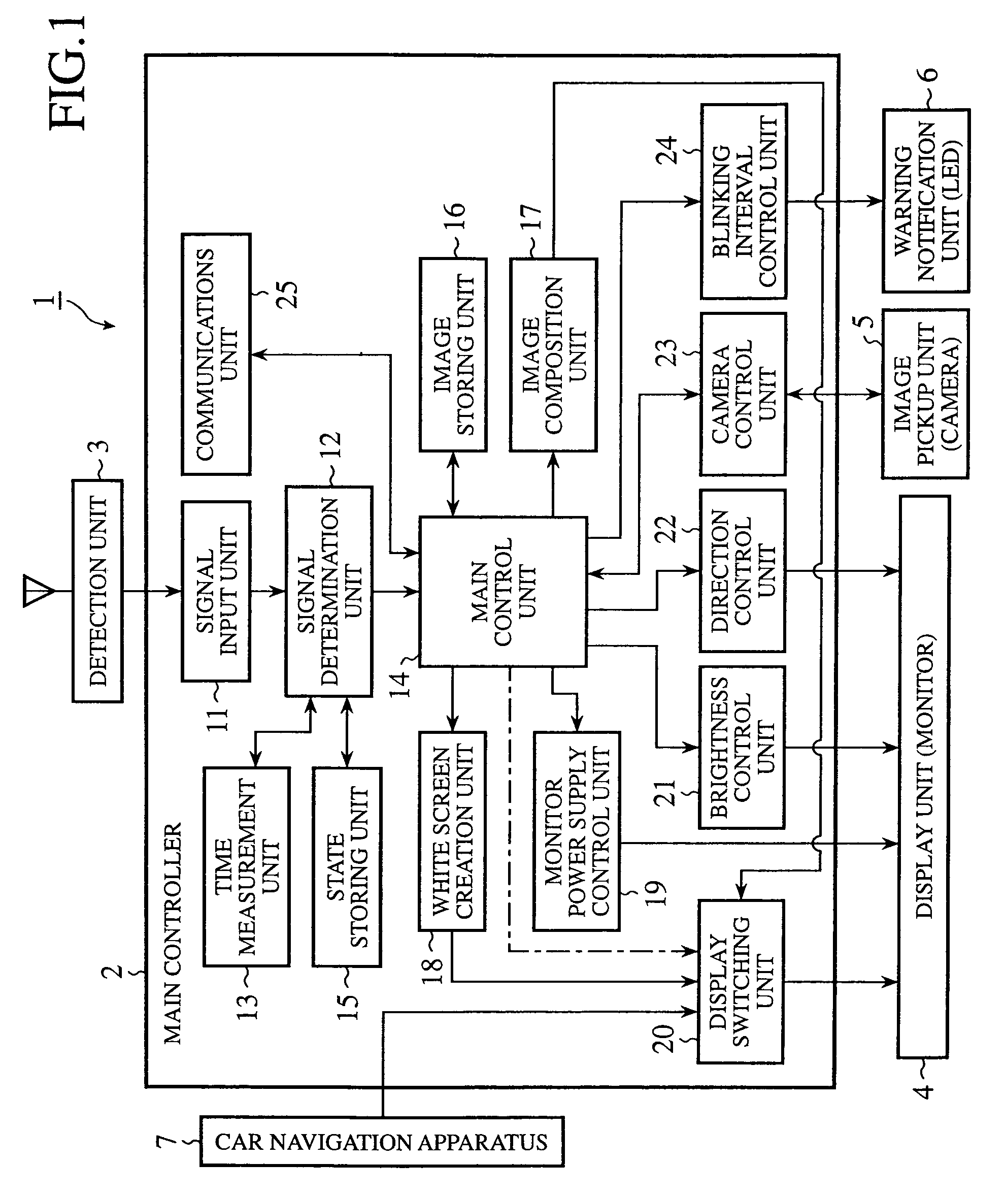
[0023]FIG. 1 is a block diagram showing an example of a vehicle safety apparatus according to embodiment 1 of the present invention. In FIG. 1, the vehicle safety apparatus 1 is attached to a vehicle (not shown) and is used in order to ensure the safety of the vehicle, such as to take a theft-prevention measure for the vehicle, as mentioned later. The vehicle safety apparatus 1 is provided with a main controller 2 connected with a detection unit (has a camera or an infrared sensor, for example) 3, a display unit (referred to as a monitor from here on) 4, an image pickup unit (or a camera) 5, and a warning notification unit (e.g., an LED) 6, and also connected with a car navigation apparatus 7. The vehicle safety apparatus shares the monitor 4 with the car navigation apparatus 7, and the camera 5 is so arranged as to pick up images of the inside and outside of the vehicle, as will be mentioned below. Two warning notification units 6 are arranged inside and outside the vehicle (e.g., ...

embodiment 2

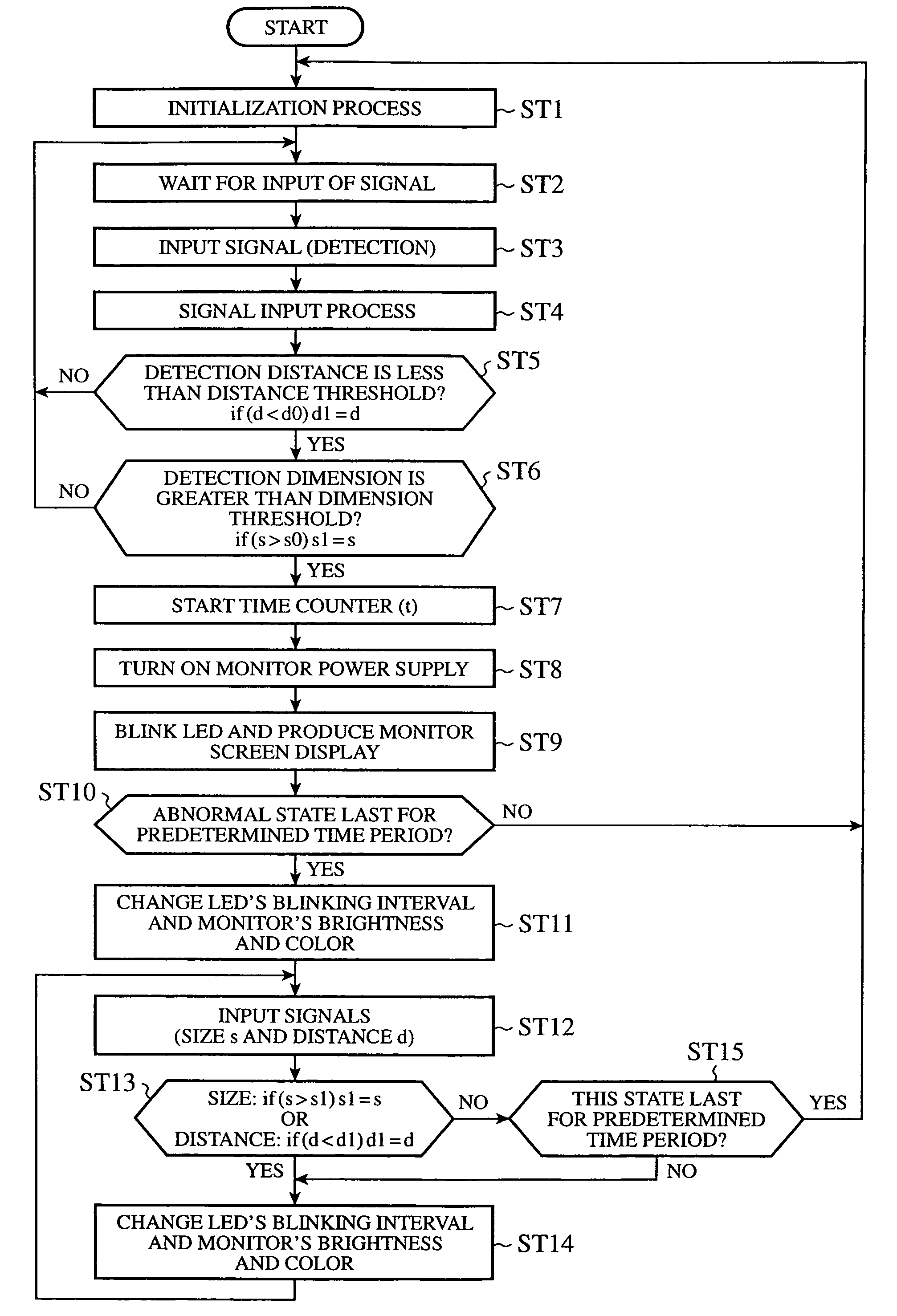
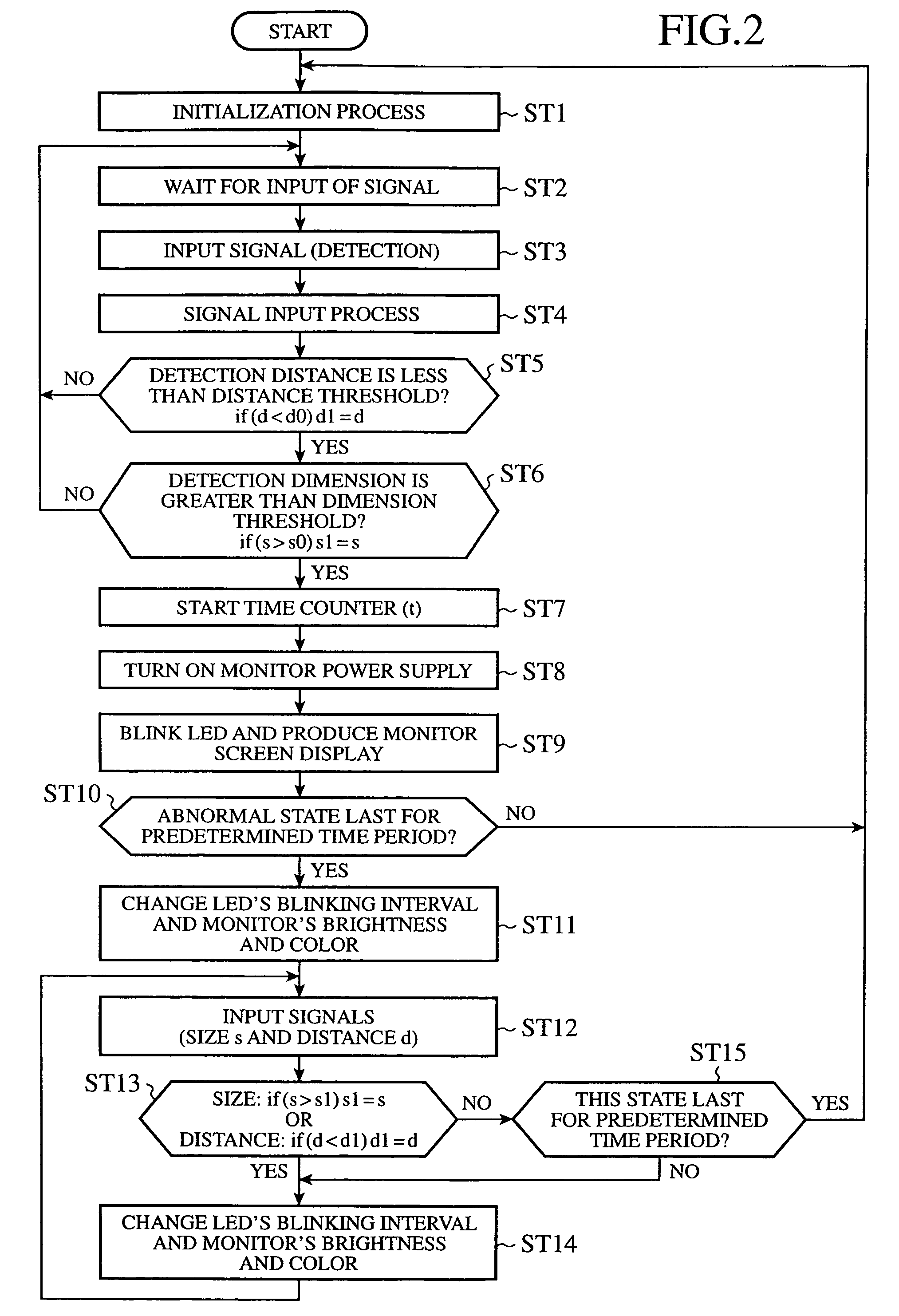
[0043]FIG. 3 is a flow chart for explaining the operation of a vehicle safety apparatus according to embodiment 2 of the present invention. In FIG. 3, the same steps as shown in FIG. 2 are designated by the same reference numerals. In step ST3 of FIG. 3, when there is an input of a monitoring signal, a signal determination unit 12 notifies an input of the monitoring signal to a main control unit 14. As a result, the main control unit 14 controls a monitor power supply control unit 19 so as to supply electric power to a monitor 4 (in a monitor power supply turning-on process of step ST21). Two or more detection units 3 are disposed, and the signal determination unit 12 determines the direction of an object with respect to the vehicle according to positions where the two or more detection units each of which sends a monitoring signal to the signal determination unit 12 are respectively arranged (in a detection direction determination process of step ST22), and sends out an object dire...

embodiment 3

[0051]FIG. 5 is a block diagram showing a vehicle safety apparatus according to embodiment 3 of the present invention and mobile terminal equipment, and FIG. 6 is a flow chart for explaining the operation of the vehicle safety apparatus according to embodiment 3 of the present invention. In FIG. 5, the same components as shown in FIG. 1 are designated by the same reference numerals. In FIG. 6, the same steps as shown in FIG. 3 are designated by the same reference numerals. In embodiment 1, no explanation of the communications unit 25 as shown in FIG. 1 is made. In the vehicle safety apparatus according to embodiment 3, a communications unit 25 operates in such a manner as mentioned below.

[0052]When a monitor power supply is turned on in step ST21, a signal determination unit 12 sends an object direction signal indicating the direction of an object to a main control unit 14, as previously explained with reference to FIG. 3. The main control unit 14 then controls a direction control u...


PUM


Abstract

When a detection unit (3) detects an approach of an object to a vehicle in which a vehicle safety apparatus is mounted, a main controller (2) determines whether a positional relationship between the vehicle and the detected object reaches a predetermined positional one. The main controller (2) can start a warning unit according to a determination result obtained thereby, and can issue a warning before the vehicle gets damaged.

Description

BACKGROUND OF THE INVENTION[0001]1. Field of the Invention[0002]The present invention relates to a vehicle safety apparatus for ensuring the safety of a vehicle, and, more particularly, to a vehicle safety apparatus for preventing a vehicle from theft or the like.[0003]2. Description of Related Art[0004]In recent years, there is a trend toward vehicle safety apparatus for ensuring the safety of a vehicle in vehicles, such as a prevention of a theft of a vehicle. Such a conventional vehicle safety apparatus (for example, a vehicle antitheft device) is so constructed as to issue a warning or the like when certain damage is inflicted on a vehicle or vehicle-mounted equipment or an accident occurs in the vehicle.[0005]As a vehicle antitheft device, there has been proposed a device for turning on a display for use in electronic equipment mounted in a vehicle when detecting an occurrence of an accident in the vehicle (refer to Japanese patent application publication (TOKKAIHEI) No. 10-154...

Claims


Application Information

Patent Timeline
IPC IPC(8): B60Q7/00B60R25/10B60R25/104B60R25/30G08B13/00G08B13/196G08B15/00
CPCB60R25/102B60R25/305B60R25/33G08B15/002B60R2325/205
Inventor OKADA, REIKONAITO, NORIHIRO
Owner MITSUBISHI ELECTRIC CORP
Why Eureka
Try Eureka