Pivot-blade cutting and retaining means for rotary mowers

a technology of rotary mowers and cutting blades, which is applied in the field of rotary mowers, can solve the problems of uneven cutting, unprofessional appearance, and less than desirable cut quality for finish-cut operations, and achieve the effect of stable cutting blade platform, cost-effective and efficient design

Active Publication Date: 2009-03-24
MTD PRODUCTS
View PDF30 Cites 22 Cited by
  • Summary
  • Abstract
  • Description
  • Claims
  • Application Information

AI Technical Summary

Benefits of technology

[0007]The present invention provides an improved pivot-blade retaining mechanism that provides a stable platform for the cutting blades while remaining cost effective and efficient in design.
[0013]In another embodiment, the invention is a method for attaching pivot-blades to a mower. The method includes placing a mounting spacer between an upper retaining plate and a lower retaining plate, wherein the mounting spacer is generally hat shaped, having a rim portion and a center extension, wherein the rim of the mounting spacer has a diameter that is larger than the diameter of the center aperture in the lower retaining plate and the center extension has a diameter that is smaller than the diameter of the center aperture in the upper retaining plate, such that the rim of the mounting spacer rests on the lower retaining plate and the center extension passes through the center aperture of the upper retaining plate so that the lower and upper retaining plates are separated by the rim of the mounting spacer. The method further includes placing end portions of at least two pivot-blades between the upper and lower retaining plates and retaining each pivot-blade between the lower and upper retaining plates with a blade mounting bolt and a nut, wherein the blade mounting bolt passes through apertures in the lower and upper retaining plates and an aperture in the mounting end of the pivot blade. The method further includes aligning center mounting apertures in the upper retaining plate and the lower retaining plate with a hole in the mounting spacer and inserting a fastener through the mounting apertures and the hole to fasten the cutting device to a spindle on the mower. In another embodiment, the invention further includes placing the pivot-blades such that a sail portion on the back edge of at least one pivot-blade faces in a downward direction and sail portion on the back edge of at least one pivot-blade faces in an upward direction to increased turbulence is created within a mower deck chamber for mulching operations.

Problems solved by technology

However, these methods provide less than desirable cut-quality for finish-cut operations.
The cutting blade would experience significant wobble that resulted in an uneven cut and unprofessional appearance.

Method used


Image

  • Pivot-blade cutting and retaining means for rotary mowers
  • Pivot-blade cutting and retaining means for rotary mowers
  • Pivot-blade cutting and retaining means for rotary mowers

Examples


Embodiment Construction

[0027]The invention will now be described in the following detailed description with reference to the drawings, wherein preferred embodiments are described in detail to enable practice of the invention. Although the invention is described with reference to these specific preferred embodiments, it will be understood that the invention is not limited to these preferred embodiments. But to the contrary, the invention includes numerous alternatives, modifications and equivalents as will become apparent from consideration of the following detailed description.

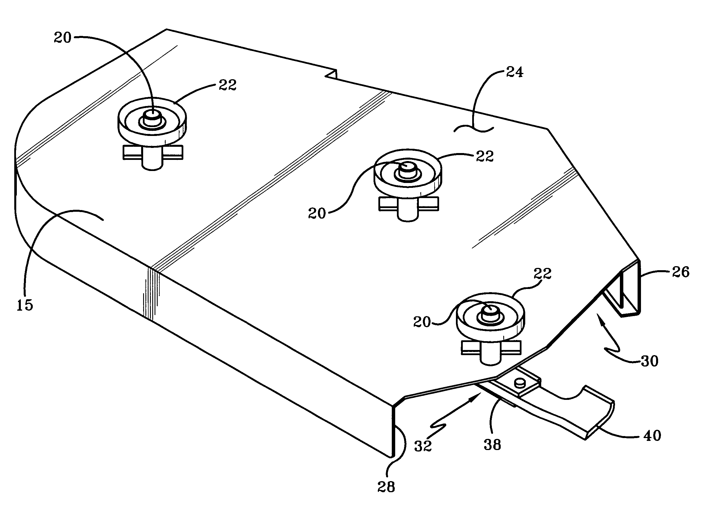
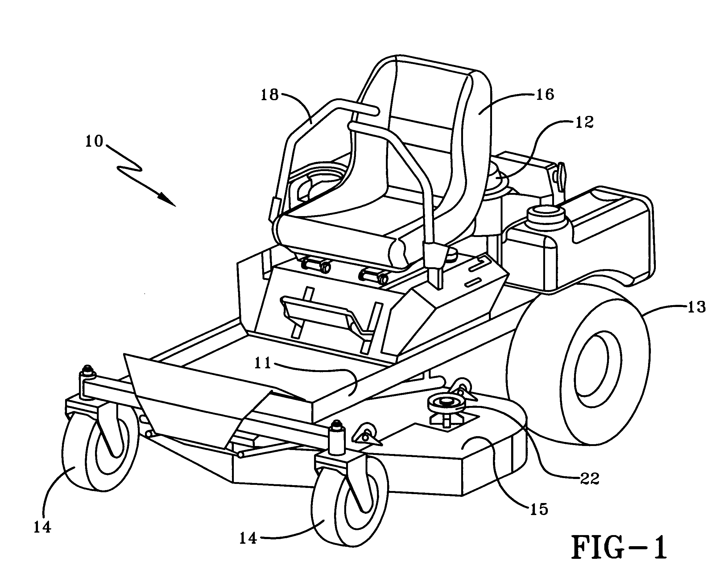
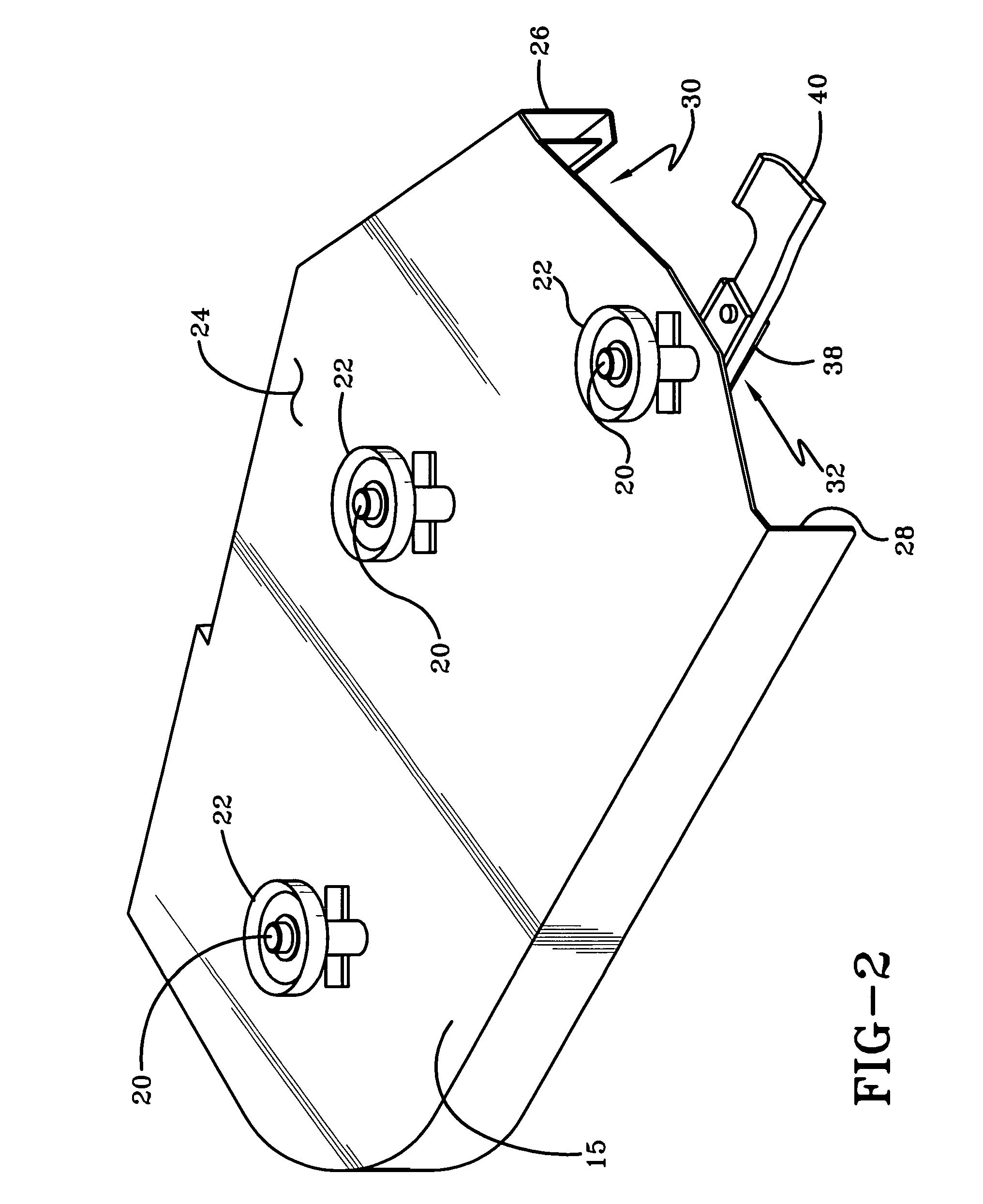
[0028]Referring to the drawings and more specifically to FIG. 1, a riding mower 10 for cutting grasses and other vegetation is illustrated. The riding mower 10 is built on a chassis 11 which supports an engine 12, a pair of drive wheels 13, and a pair of caster mounted follower wheels 14. A mower deck 15 is adjustably suspended from the chassis 11 of the mower 10 through vertical height adjustment rods (not shown) between the drive ...


PUM


Abstract

A cutting device configured to attach to a spindle of a mower. The cutting device includes at least two pivot-blades and a blade mounting assembly. The blade mounting assembly has an upper retaining plate, a lower retaining plate, and a mounting spacer positioned at least partially between the upper retaining plate and the lower retaining plate, wherein end portions of the pivot-blades are retained between the upper and lower retaining plates.

Description

CROSS-REFERENCE TO RELATED APPLICATION[0001]This application claims the priority benefit of U.S. Provisional Patent Application No. 60 / 644,550 filed Jan. 18, 2005.BACKGROUND OF THE INVENTION[0002]1. Field of Invention[0003]This invention relates to the field of mowers and, more specifically, to a pivot-blade retaining mechanism for such mowers.[0004]2. Description of Related Art[0005]For many years, lawn mower blades were simply bolted on to the bottom of a rotating shaft. As the blades themselves were a little more than straight pieces of sharpened stamped steel, and as all of the forces on the blade were unidirectional, this method of interconnection worked quite well. When the requirements for passing torque to the blade increased, manufacturers adapted varying techniques to include some sort of adapter between the blade and the shaft in order to physically connect the blade. Typically, these methods used a single mounting plate or disc and attached the blade with mounting bolts ...

Claims


Application Information

Patent Timeline
Patent Type & Authority Patents(United States)
IPC IPC(8): A01D34/00
CPCA01D34/733
Inventor EAVENSON, SR., JIMMY N.STEVENS, JOELMORSE, DAN
Owner MTD PRODUCTS
Why Eureka
Try Eureka