Novel converter tool platform

A converter and tooling technology, applied in the field of new converter tooling platform, can solve the problems of narrow space, long construction period, waste of structural materials, etc., and achieve the effect of reasonable structure design, convenient disassembly and assembly, and material saving

Pending Publication Date: 2017-05-31
TIANJIN 20 CONSTR
View PDF5 Cites 1 Cited by
  • Summary
  • Abstract
  • Description
  • Claims
  • Application Information

AI Technical Summary

Problems solved by technology

[0003] 1. To install a converter, a tooling platform needs to be manufactured, installed and dismantled, and the construction period is long;
[0004] 2. The tooling platform is welded and connected. During the dismantling process, due to the small space, it needs to be destructively dismantled, so that the platform cannot be completely reused;
[0005] 3. The design of the tooling platform is only for a specific converter that needs to be installed, and the scope of application is small
[0006] The invention patent with the application number 201310378949.0 discloses a detachable converter tooling platform, and its defects are (1) the retractable steel beam is composed of I-shaped beam 1, ][-shaped beam 2, liner between beams, and movable rib seat Composition, there are many components, and the assembly is difficult; in order to ensure the strength of the beam, the strength of the ][-type beam 2 is much greater than the strength of the I-shaped beam 1, resulting in waste of structural materials for the ][-type beam 2, and in order to ensure the tight connection between the beams The liner between the beams is designed, which is equivalent to doing some useless work
(2) The center line of the column is consistent with the center of the steel beam, and the height of the adjustable steel beam changes with the change of the furnace type. Because the steel beam is located in the column, in order to avoid the interference between the furnace shell and the steel beam, the height of the steel beam is reduced. In the mechanical calculation In addition, the cantilever height of the upper column of the steel beam is increased, thereby reducing the overall stability of the tooling platform

Method used


Image

  • Novel converter tool platform
  • Novel converter tool platform
  • Novel converter tool platform

Examples


Embodiment Construction

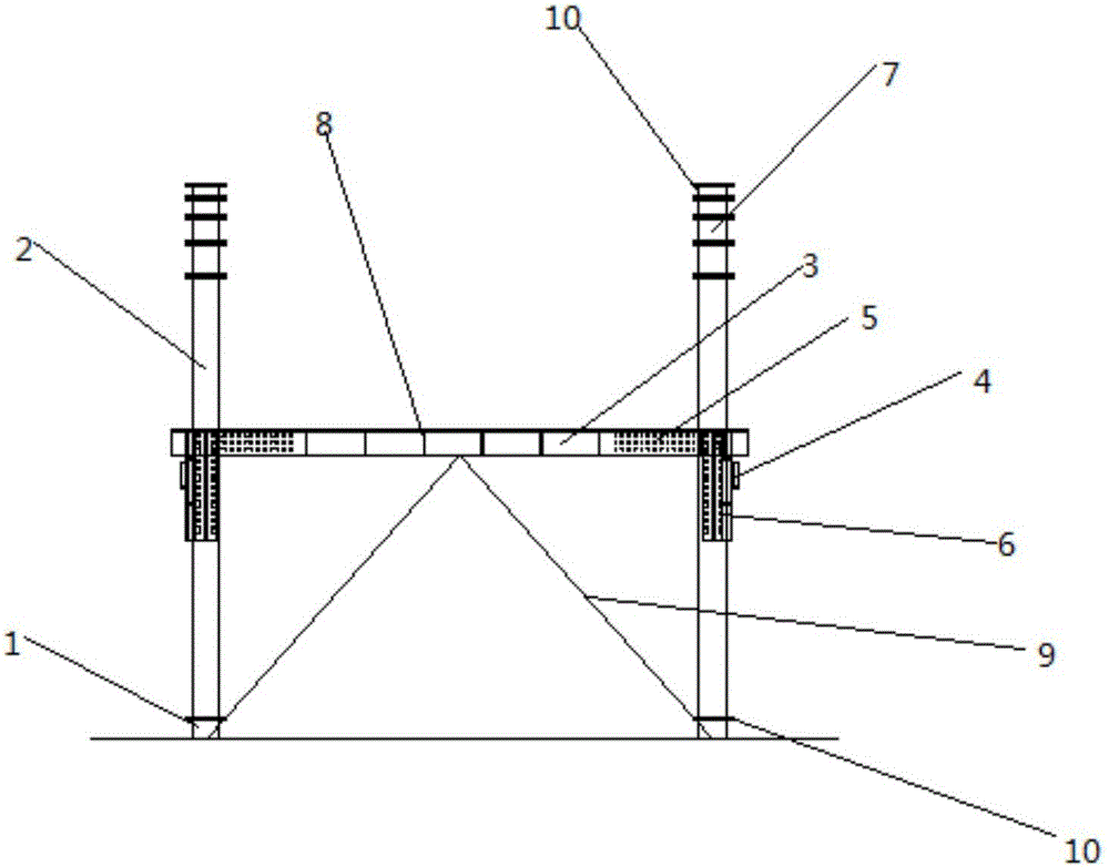
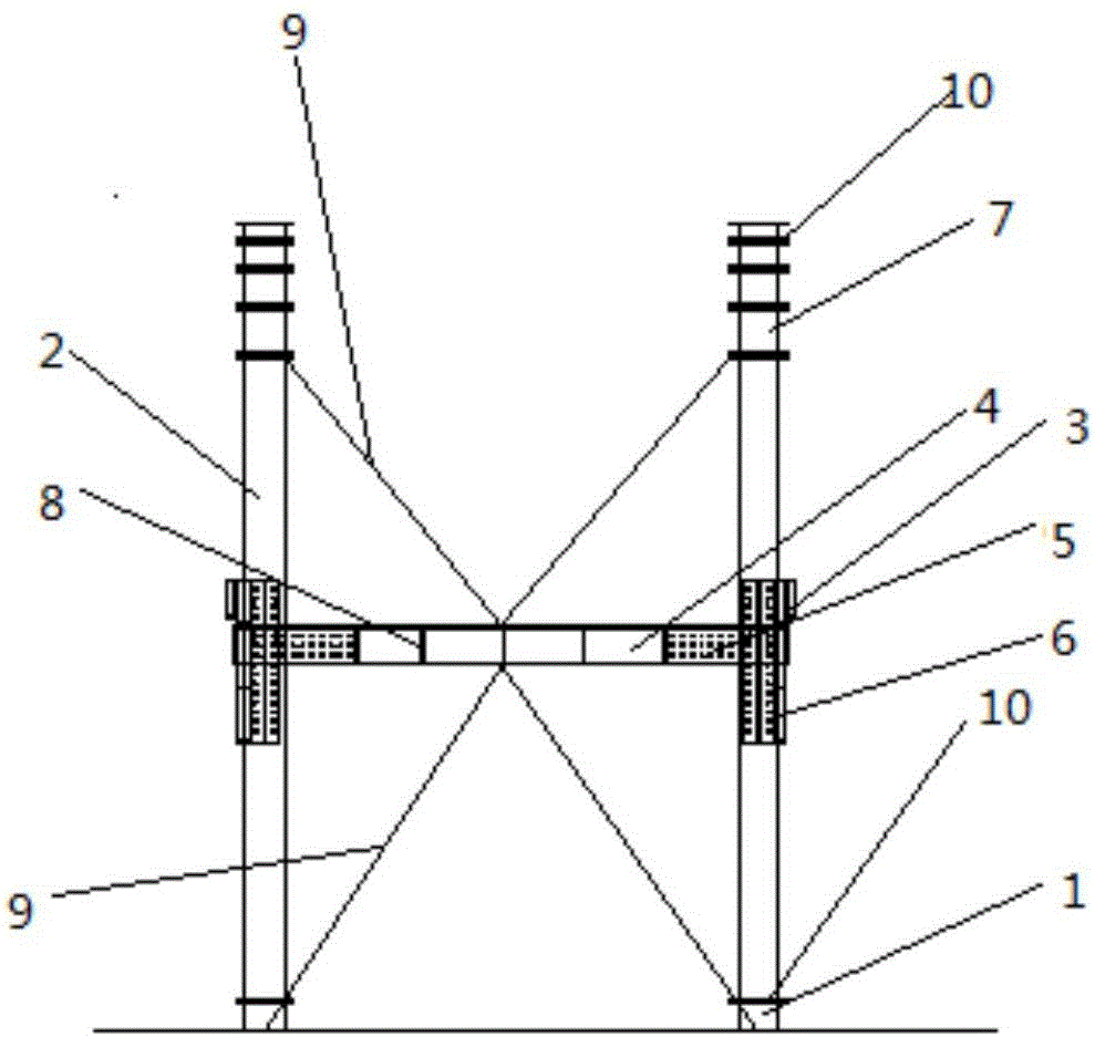
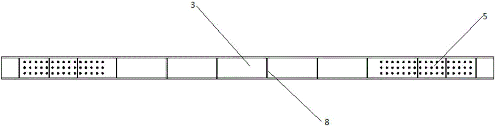
[0025] like Figure 1-5 As shown, the present invention provides a novel converter tooling platform, including a frame structure composed of adjustable steel columns, beam one 3 and beam two 4;

[0026] The adjustable steel column is formed by sequentially connecting the bottom column 1, the base column 2 and the adjustment column 7, and the base column 2 is fixed with a bolt reinforcement plate 6 for connecting the first beam 3 and the second beam 4, and the bolt reinforcement plate 6 is fixed on the base On the outer side of the column 2, the adjusting column 7 includes adjusting column sections with different heights;

[0027] The height adjustment of the adjustable steel column is realized by selecting adjustable column sections or combinations thereof with different heights;

[0028] Both ends of beam one 3 and beam two 4 have connection plates 5 . Both the connecting plate 5 and the bolt reinforcing plate 6 have a plurality of bolt holes, the connecting plate 5 and the...


PUM


Abstract

The invention provides a novel converter tool platform which comprises adjustable steel columns and a frame structure composed of first cross beams and second cross beams. Each adjustable steel column is formed by sequentially connecting a bottom column, a base column and an adjustment column. The base columns are fixedly provided with bolt reinforcement plates which are used for connecting the first cross beams and the second cross beams and fixed to the outer side faces of the base columns. Each adjustment column comprises adjustment column sections of different heights, and the height of each adjustment column can be adjusted by selecting or combining the adjustment column sections of the different heights. The two ends of the first cross beams and the two ends of the second cross beams are each provided with a connecting plate. The connecting plates and the bolt reinforcement plates are each provided with a plurality of bolt holes and are connected through bolts. The first cross beams and the second cross beams are separately located on the adjacent side faces of the frame structure, are different in height and are arranged in a staggered mode. The novel converter tool platform has the beneficial effects of being reasonable in structural design, convenient to dismount and mount, firm and capable of saving materials.

Description

technical field [0001] The invention relates to a novel converter tooling platform. Background technique [0002] In the installation process of the converter body equipment using the translation method, it is necessary to design a large tooling platform for the translation of the converter body. Since the weight of the main body of the converter reaches hundreds of tons, the tooling platform needs to use a large amount of steel for on-site fabrication, installation, and dismantling. At the same time, the platforms around the converter are completed one after another after the main body of the converter is in place, resulting in a narrow space around the converter. The platform needs to be destroyed Permanent demolition will eventually result in a large amount of steel that cannot be reused and waste of resources. All the above factors lead to a large amount of cost of measures and waste of resources during the converter installation process. At present, there are deficien...

Claims


Application Information

Patent Timeline
Patent Type & Authority Applications(China)
IPC IPC(8): E04G1/20C21C5/46
CPCC21C5/4633E04G1/20
Inventor 杜军科菅宏伟徐彬
Owner TIANJIN 20 CONSTR
Why Eureka
Try Eureka