Parallel link machine design

a parallel link and machine design technology, applied in the direction of machine supports, applications, gearing, etc., can solve the problems of saving cost and error budget, and achieve the effects of convenient calibration, convenient use of working volume, and simplified kinematics of parallel link mechanisms

Inactive Publication Date: 2009-03-24
SHINNIPPON KOKI
View PDF25 Cites 10 Cited by
  • Summary
  • Abstract
  • Description
  • Claims
  • Application Information

AI Technical Summary

Benefits of technology

[0013]It is an object of the invention to simplify the kinematics of parallel link mechanisms to make them easier to calibrate, deliver a more useable working volume in a smaller package size, and in particular to reduce their mechanical complexity in order to reduce their cost.
[0014]It is a further object of this invention to provide for a more ergonomic machine package that gives ready access to the workspace, is easy to maintain and is lightweight without sacrificing stiffness.
[0015]It is a first aspect of this invention to use a friction drive concept to change the effective lengths of the struts, which can then be low cost and lightweight. This technique avoids the mechanical complexity in otherwise restraining the torque generated by the more typical screw drive strut. It also enables the simple integration of a strut length encoder. It also facilitates very long struts and / or very fast movement by reducing the static and inertial mass.

Problems solved by technology

The simplification saves the cost and the error budget of what otherwise would be a redundant axis.

Method used


Image

  • Parallel link machine design
  • Parallel link machine design
  • Parallel link machine design

Examples


Embodiment Construction

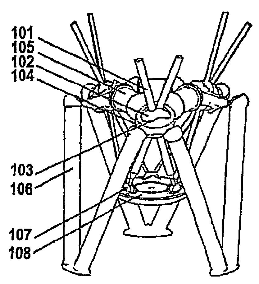
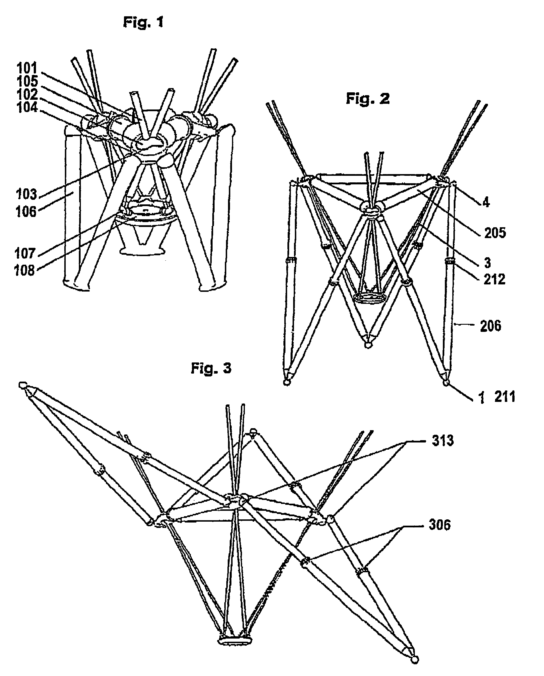
[0070]An embodiment of a 6 node hexapod is shown in FIG. 1. The struts (e.g. 101) cross over in, and can pass through bifurcated drive spheres (e.g. 102), supported in sockets (e.g. 104). The other ends of the struts join in pairs at bifurcated spherical joints (e.g. 107) connected with each other by sub-frame 108. As will be described in detail hereinafter, each strut 101 has a semicircular section and has friction wheel runners bonded to its sides. Each bifurcated drive sphere 102 allows two struts 101 to pass through it as near to its split line as practical. Each drive sphere 102 is journalled in a spherical socket 104 having bi-lobar socket windows 103 that permit symmetrical articulation of the strut pair, traversing each drive sphere 102. The sockets 104 are formed by corner moldings that connect to spacer struts (e.g. 105) which define the distance between drive sphere focal points and can be adjustable in length and to respective support legs. (e.g. 106). The bifurcated joi...


PUM

PropertyMeasurementUnit
length erroraaaaaaaaaa
displacement erroraaaaaaaaaa

Abstract

A hexapod machine is disclosed in which six adjustable length struts couple to a controllably moveable platform at three triangularly spaced locations at each of which a pair of struts couple together and to the platform at a bifurcated universal joint. The struts extend away from the platform and through machine nodes defined at triangularly spaced-apart locations in a machine sub-frame, and at each such node a strut extending from one platform location and the next adjacent strut from the next adjacent platform location come together and cross each other in respective hemispheres of a bifurcated sphere journalled for multidirectional pivotal movement in a socket in the sub-frame. The hemispheres each contain a motor which is frictionally engaged with the respective strut so as to enable it to be driven through the hemisphere to adjust its effective length. By control of the motors, the platform position and orientation can be adjusted in space. Also disclosed is a pentapod machine in which a tripod with three adjustable legs defines the position of a first tool support, and the position of a second spaced-apart tool support is defined by two adjustable legs, a tool being supported between said two supports.

Description

FIELD OF THE INVENTION[0001]This invention concerns improvements in parallel link machine design. Parallel link mechanisms, in contrast to serial link mechanisms, function in dependence upon the movements of plural linkages working in concert to determine a position, whereas in serial link mechanisms each linkage operates independently.[0002]The Hexapod (see for example WO-A-9217313) is an example of a parallel link machine.[0003]The invention provides new configurations of parallel link mechanisms, which confer advantages of dexterity, compactness, ergonomics and value engineering.[0004]In one aspect of the invention, a new ‘bifurcated’ drive mechanism is proposed for a Hexapod. It enables two struts to be driven through the same notional focal point, thereby minimising the number of nodes that need to be supported and calibrated. It also enables a snide separation of nodes for a given package size, which improves the stiffness and accuracy. A new kinematic arrangement is also prop...

Claims


Application Information

Patent Timeline
Patent Type & Authority Patents(United States)
IPC IPC(8): F16M11/00B25J11/00B23Q1/01B23Q1/54B23Q3/155B23Q5/38B23Q11/00B23Q11/08B25J17/00B25J17/02F16C11/06F16H13/04F16H19/02F16H21/44F16H21/46H02K7/116
CPCB23Q1/015B23Q1/5462B23Q3/15506B23Q5/385B23Q11/0032B25J17/0216B25J17/0266B25J9/0057B23Q11/08Y10T409/309576F16H19/025Y10T409/307672
Inventor BAILEY, RALPH-PETER STEVEN
Owner SHINNIPPON KOKI
Why Eureka
Try Eureka