Apparatus for the latching and unlatching of a load

a technology for latching and unlatching equipment, applied in the direction of load-engaging elements, thin material handling, transportation and packaging, etc., can solve the problems of inability to provide an audible warning to personnel, secondary lines are more susceptible to being inadvertently pulled, and damage to surrounding personnel, so as to reduce operating time, safety and cost concerns, and ensure the safety of the load

Inactive Publication Date: 2009-03-24
MARLER JOSEPH E
View PDF13 Cites 20 Cited by
  • Summary
  • Abstract
  • Description
  • Claims
  • Application Information

AI Technical Summary

Benefits of technology

[0009]It is an object of the invention to provide an improved apparatus with a latching and unlatching mechanism for the safe and...

Problems solved by technology

In addition the noise at these sites may be at a level that makes it difficult to provide an audible warning to personnel if something has mistakenly occurred, such as the premature release of a load from a lifting line.
Another problem relates to the manner in which the load is released from the latching device.
Such secondary lines ...

Method used


Image

  • Apparatus for the latching and unlatching of a load
  • Apparatus for the latching and unlatching of a load
  • Apparatus for the latching and unlatching of a load

Examples


Embodiment Construction

[0055]Without any intent to limit the scope of the invention, the preferred embodiments of the invention are illustrated in the Figures and described hereinbelow.

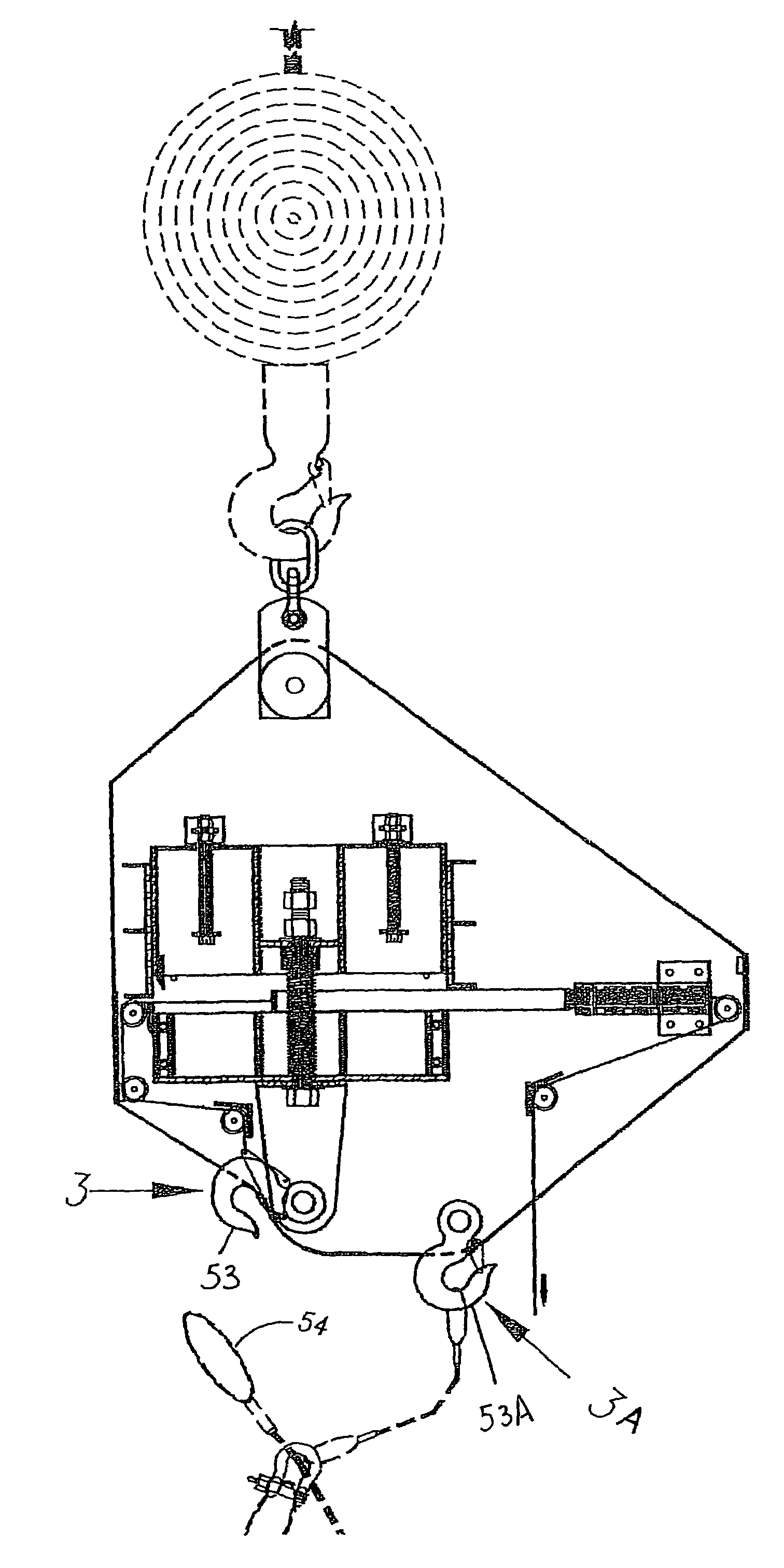
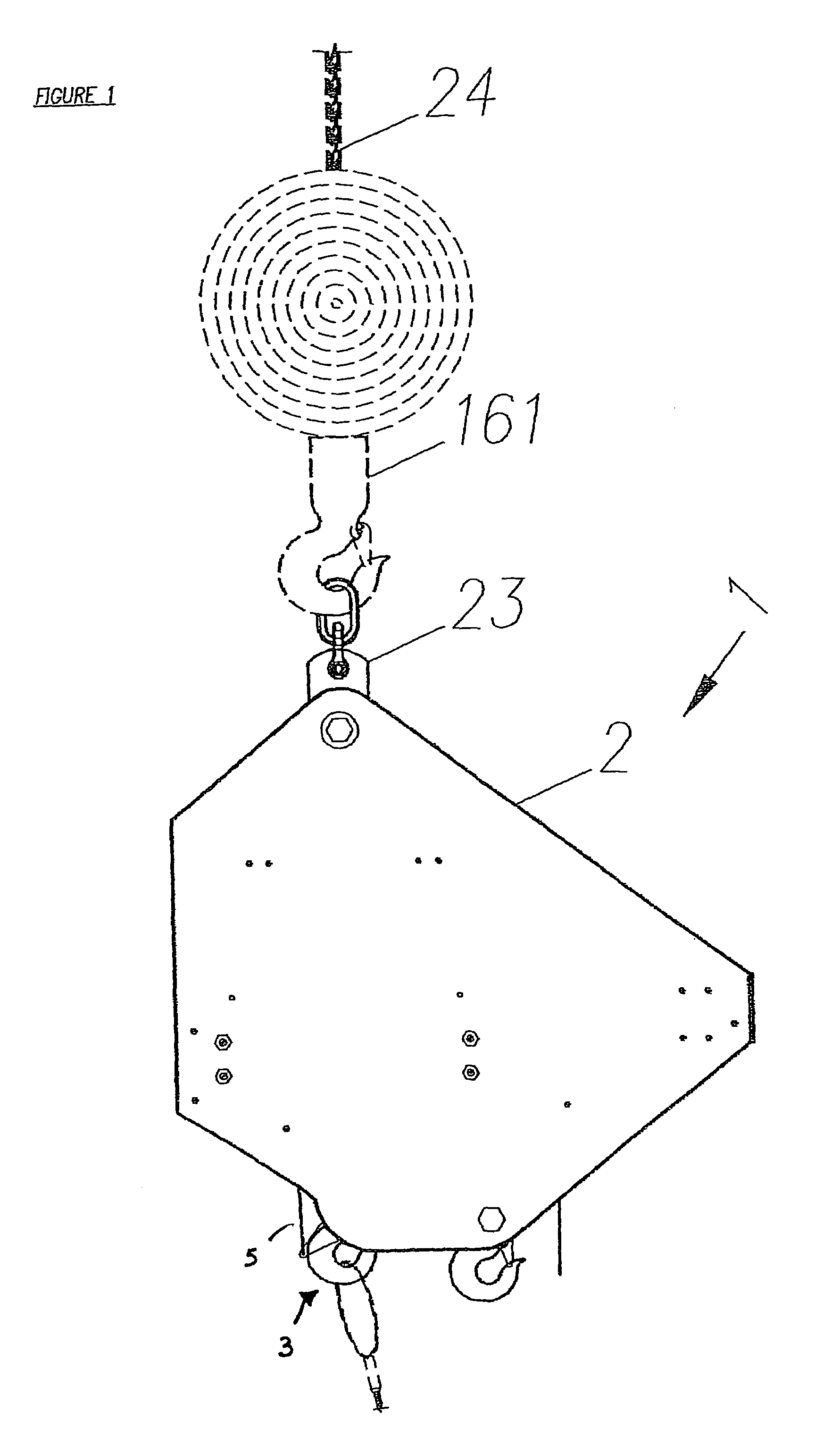
[0056]Referring to FIGS. 1-6 a preferred embodiment of the invention is illustrated. In its basic form the latching and unlatching apparatus 1 includes a housing 2, a load-engaging assembly 3; a load-activated lock assembly 8, a cable 4 having its end 5 operatively attached to load-engaging assembly 3 and it opposite end attached to load-activated lock assembly 8, and a load release line 6 for unlatching a load 7 attached to load-activated lock assembly 8.

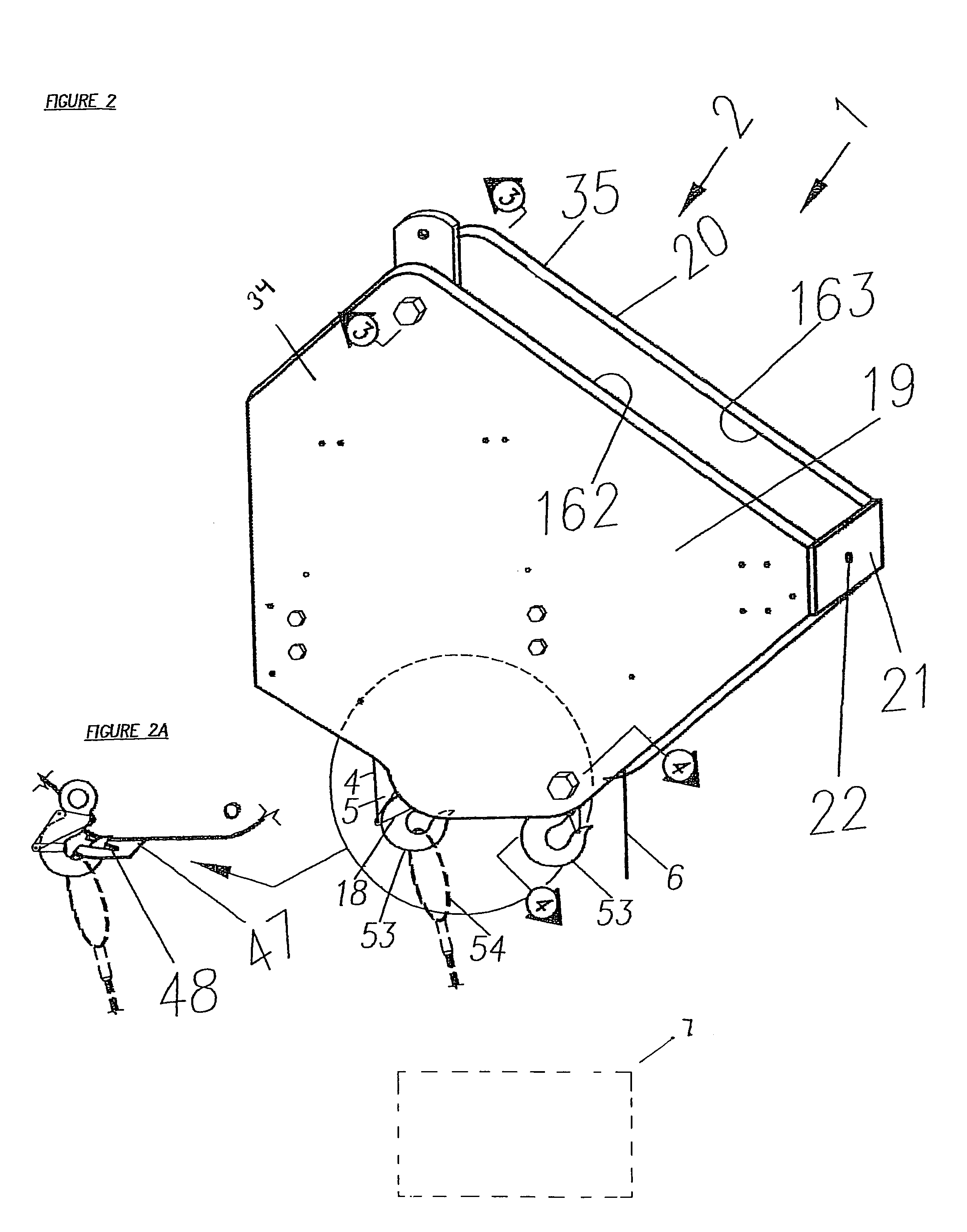
[0057]As illustrated in FIG. 2, housing 2 includes parallel front plate 19 and back plate 20 separated from one another by spacer plate 21a sufficient distance to house at least in part the load-engaging assembly 3 and the load-activated lock assembly 8. As depicted by FIGS. 5, 11, and 1A, the spacing between front plate 19 and back plate 20 is also maintained by brackets ...


PUM


Abstract

An improved apparatus for latching and unlatching a load from a sling comprises a housing attachable to a load lift line extending from a crane or other similar equipment. Contained at least partially within the housing is a load engaging assembly including a latch, such as a conventional sling hook used to attach a load containing sling. The load engaging assembly further includes a latch attachment assembly and an unlatching trigger assembly. The apparatus further includes a load activated lock operatively attached to the latch attaching assembly to latch and unlatch the load engaging assembly. The load activated lock includes a support structure affixed to the housing, a latch activating member slidably mounted on the support structure and a movable locking structure positioned within the housing and operatively adjacent the latch activating member to engage and prevent latch activating member from sliding movement when a load is applied to the latch. The apparatus further includes a compression switch affixed to the housing at a position to be activated when a load of a predetermined weight is attached to the latch. The apparatus further includes at least one remote controlled relay switches electrically connecting the compression switch, or alternatively a second compression switch, to the power unit of an adjustable clutch motor having a rotating drive shaft. The apparatus also including a remote control broadcasting device to emit predetermined signals to close at least one of the remote controlled relay switches. The drive shaft is attached a reel line affixed at its opposite end to the latch activating member. The drive shaft when activated will cause the reel line retract to operatively cause the latch activating member to move and cause the latch to be positioned for releasing the sling from the latch.

Description

RELATED APPLICATION[0001]This is a continuation in part of U.S. Ser. No. 10 / 906,129, filed Feb. 3, 2005 now U.S. Pat. No. 7,032,943 and entitled “Apparatus for the Latching and Unlatching of a Load,” and is hereby incorporated by reference in its entirety.BACKGROUND OF THE INVENTION[0002]1. Field of the Invention[0003]This invention relates in general to apparatus for latching and unlatching a load from a sling and, more particularly, to such apparatus having a locking structure and one or more safety devices activated by the application of a force caused by the lifting of the load.[0004]2. Prior Art[0005]In construction and other commercial or industrial environments it is necessary to move a load from one place to another place. This movement is facilitated by the use of cranes having a lifting line to which slings can be attached for securing the load to the lifting line. Various devices used to latch and unlatch a load from these slings are well known in the prior art. In the de...

Claims


Application Information

Patent Timeline
IPC IPC(8): B66C1/34
CPCB66C1/34Y10S294/905Y10S294/907
Inventor MARLER, JOSEPH E.
Owner MARLER JOSEPH E
Why Eureka
Try Eureka